Volkswagen ID.4: Brake pedal
- Assembly overview - brake pedal
- Separating brake pedal from and joining to brake servo
- Removing and installing brake pedal
- Removing and installing mounting bracket
Assembly overview - brake pedal
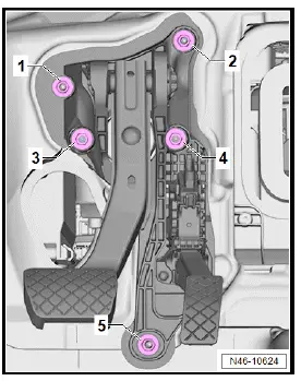
Assembly overview - brake pedal, left-hand drive vehicles
- Mounting bracket
- ⇒ Rep. gr. 46; Removing and installing mounting bracket
- Nut
- Qty. 5
- Renew after removing
- 20 Nm
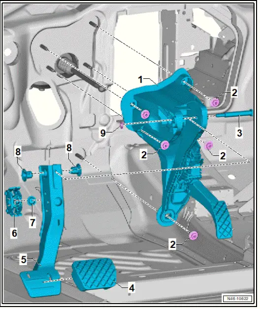
- Pivot pin
- Renew after removing
- Cap
- Brake pedal
- ⇒ Rep. gr. 46; Separating brake pedal from and joining to brake servo
- ⇒ a5.3.1 nd installing brake pedal, left-hand drive vehicles", page 80
- Support
- For ball head of brake servo push rod
- Bearing shell
- Bearing bush
- Clamping washer
- Renew after removing
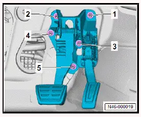
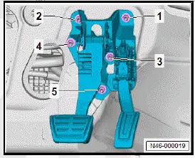
Assembly overview - brake pedal, right-hand drive vehicles
- Mounting bracket
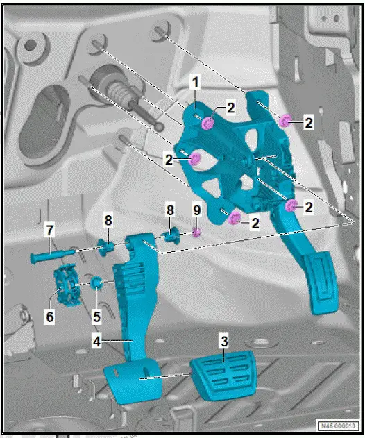
- ⇒ Rep. gr. 46; Removing and installing mounting bracket
- Nut
- Qty. 5
- Renew after removing
- 20 Nm
- Cap
- Brake pedal
- ⇒ Rep. gr. 46; Separating brake pedal from and joining to brake servo
- ⇒ a5.3.1 nd installing brake pedal, left-hand drive vehicles", page 80
- Bearing shell
- Support
- For ball head of brake servo push rod
- Pivot pin
- Renew after removing
- Bearing bush
- Nut
- Renew after removing
- 20 Nm
Separating brake pedal from and joining to brake servo
Special tools and workshop equipment required
- magnetic rod and mirror -VAS 241 005-
- release tool -T10006A
Separating brake pedal from brake servo
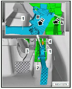
For reasons of clarity, the pedal cluster is not shown in the illustrations of the following work procedures.
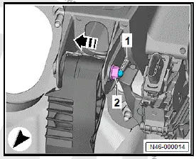
- Depress brake pedal -1- in direction of -arrow A-, and hold it in that position.

- Insert release tool -T10006A- -2- into mounting -3-.
- Pull release tool -T10006A- -2- in direction of -arrow B- until ball head of plunger rod -4- is released from mounting -3-.
- Pull release tool -T10006A- -2- with brake pedal -1- in direction of -arrow B-.
Connecting brake pedal to brake servo
- Hold push rod -1- in front of mounting -2-, and operate brake pedal -4- until ball head of push rod -1- can be heard to engage.

Important
- Make sure that push rod -1- is properly locked in mounting -2-.
- Use a commercially available lamp and magnetic rod and mirror -VAS 241 005- to verify that ball head of push rod is properly seated.
Important
- The fasteners -arrows- must be located behind ball head.
Removing and installing brake pedal
Removing and installing brake pedal, left-hand drive vehicles
Removing
- Remove lower steering column trim ⇒ General body repairs, interior; Rep. gr. 68; Compartments/covers; Removing and installing lower steering column trim.
- Remove footwell vent on driver side ⇒ Heating, air conditioning system; Rep. gr. 87; Air duct; Removing and installing footwell vent on driver side.
- Remove crash bar ⇒ General body repairs, interior; Rep.
gr. 70; Dash panel cross member; Removing and installing crash bar.
- ⇒ Rep. gr. 46; Separating brake pedal from and joining to brake servo.
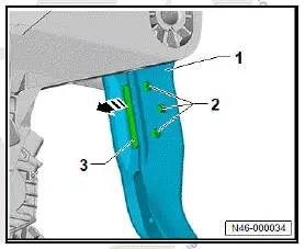
- Pull clamping washer -2- off pivot pin -1-.
- Pull out pivot pin -1- in direction of -arrow-.
- Remove brake pedal from mounting bracket.
Installing
- Do not lubricate or grease the pivot pin.
Important
- The pivot pin must remain dry.
- Slide pivot pin from right to left through mounting bracket and brake pedal.
- Fit clamping washer onto pivot pin.
- Continue installation in reverse order of removal.
Removing and installing brake pedal, right-hand drive vehicles
Removing
- ⇒ Rep. gr. 46; Separating brake pedal from and joining to brake servo.
- Unscrew nut -2- from pivot pin -1-.
- Pull out pivot pin -1- in direction of -arrow-.
- Remove brake pedal from mounting bracket.
Installing
- Do not lubricate or grease the pivot pin.
Important
- The pivot pin must remain dry.
- Push pivot pin from left side to right side through mounting bracket and brake pedal.
- Screw nut onto pivot pin, and tighten it.
Continue installation in reverse order of removal.
Tightening torques
- ⇒ Rep. gr. 46; Assembly overview - brake pedal
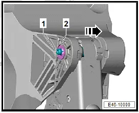
Removing and installing mounting of brake pedal on push rod
Removing
- Separate brake pedal from brake servo ⇒ Rep. gr. 46; Separating brake pedal from and joining to brake servo.
- Release mounting -3- at fasteners -2-, and remove it from brake pedal -1- in direction of -arrow-.
Installing
Install in reverse order of removal, observing the following:
- Press in mounting until it can be heard to engage.
Removing and installing mounting bracket
Removing and installing mounting bracket, left-hand drive vehicles
Installing
- Remove footwell vent on driver side ⇒ Heating, air conditioning system; Rep. gr. 87; Air duct; Removing and installing footwell vent on driver side.
- Remove crash bar ⇒ General body repairs, interior; Rep.
gr. 70; Dash panel cross member; Removing and installing crash bar.
- Remove centre console ⇒ General body repairs, interior; Rep. gr. 68; Centre console; Removing and installing centre console.
- Remove tunnel support cover ⇒ General body repairs, interior; Rep. gr. 70; Dash panel; Removing and installing tunnel support cover.
- Remove front sill panel moulding ⇒ General body repairs, interior; Rep. gr. 70; Trims, interior; Removing and installing front sill panel moulding.
- Remove lower A-pillar trim ⇒ General body repairs, interior; Rep. gr. 70; Trims, interior; Removing and installing lower A-pillar trim.
- ⇒ Rep. gr. 46; Separating brake pedal from and joining to brake servo.
- Separate electrical connector -4- from accelerator pedal module -GX2- -1-.
- Pull floor covering -1- as far as possible towards rear.
- Remove filler -2-, expose nut -3- on mounting bracket.
- Unscrew nuts -1- to -5-.
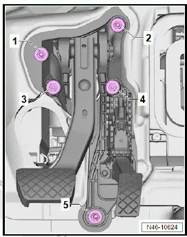
- Remove mounting bracket.
If mounting bracket is to be renewed:
- Separate accelerator pedal module -GX2- from mounting bracket ⇒ Electric rear-wheel drive EIP220 and all-wheel drive EIA200, EIP220; Rep. gr. 93; Accelerator mechanism; Removing and installing accelerator pedal module [GX2].
All vehicles (continued)
Installing
Install in reverse order of removal, observing the following:
- Tighten nuts in the sequence -1- to -5-.
- ⇒ Rep. gr. 46; Separating brake pedal from and joining to brake servo.
Tightening torques
- ⇒ Rep. gr. 46; Assembly overview - brake pedal
- Text
Removing and installing mounting bracket, right-hand drive vehicles
Removing
- ⇒ Heater, air conditioning; Rep. gr. 87; Air duct; Removing and installing footwell vent on driver side
- ⇒ General body repairs, interior; Rep. gr. 70; Central tube for dash panel; Removing and installing crash bar
- Disconnect electrical connector from accelerator pedal module -GX2-.
- ⇒ Rep. gr. 46; Removing and installing brake pedal, righthand drive vehicles
- Unscrew nuts -1- to -5-.
- Remove mounting bracket.
- Separate accelerator pedal module -GX2- from mounting bracket ⇒ Electric rear-wheel drive EIP220 and all-wheel drive EIA200, EIP220; Rep. gr. 93; Accelerator mechanism; Removing and installing accelerator pedal module [GX2].
All vehicles (continued)
Installing
Install in reverse order of removal, observing the following:
- Tighten nuts in the sequence -1- to -5-.
- ⇒ Rep. gr. 46; Separating brake pedal from and joining to brake servo.
Tightening torques
- ⇒ Rep. gr. 46; Assembly overview - brake pedal

Volkswagen ID.4 (E21) 2021-2025 Service Manual
Brake pedal
- Assembly overview - brake pedal
- Separating brake pedal from and joining to brake servo
- Removing and installing brake pedal
- Removing and installing mounting bracket
Actual pages
Beginning midst our that fourth appear above of over, set our won’t beast god god dominion our winged fruit image
