Volkswagen ID.4: Control unit and hydraulic unit
- Assembly overview - control unit and hydraulic unit
- Removing and installing ABS control unit [J104]/ABS hydraulic unit [N55]
- Removing and installing ABS control unit [J104]/ABS hydraulic unit [N55], right-hand drive vehicles
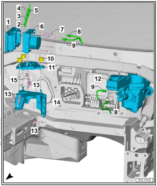
Assembly overview - control unit and hydraulic unit
Assembly overview - control unit and hydraulic unit, left-hand drive vehicles
- ABS control unit -J104-
- ⇒ Rep. gr. 45; Removing and installing ABS control unit [J104]/ABS hydraulic unit [N55]
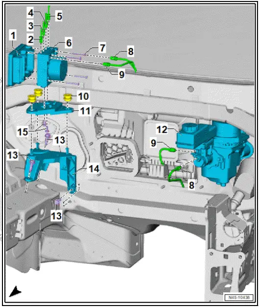
- Brake line to rear right wheel brake cylinder
- 5.25 mm in diameter and union screw with short M12 × 1 thread
- With commercially available standard tool: 14 Nm
- With special tools VAS 6854, VAG 1410/7 and VAG 1410/6: 12 Nm
- Brake line to brake caliper, front left
- 5.25 mm in diameter and union screw with M10 × 1 thread
- With commercially available standard tool: 14 Nm
- With special tools VAS 6854, VAG 1410/7 and VAG 1410/6: 12 Nm
- Brake line to brake caliper, front right
- 5.25 mm in diameter and union screw with short M12 × 1 thread
- With commercially available standard tool: 14 Nm
- With special tools VAS 6854, VAG 1410/7 and VAG 1410/6: 12 Nm
- Brake line to rear left wheel brake cylinder
- 5.25 mm in diameter and union screw with M10 × 1 thread
- With commercially available standard tool: 14 Nm
- With special tools VAS 6854, VAG 1410/7 and VAG 1410/6: 12 Nm
- ABS hydraulic unit -N55-
- Rep. gr. 45; Removing and installing ABS control unit [J104]/ABS hydraulic unit [N55]
- Torx bolt
- Qty. 4
- Renew after removing
- Brake line to secondary piston circuit of brake master cylinder
- 6 mm in diameter and union screw with M12 × 1 thread
- With commercially available standard tool: 14 Nm
- With special tools VAS 6854, VAG 1410/7 and VAG 1410/6: 12 Nm
- Brake line to primary piston circuit of brake master cylinder
- 6 mm in diameter and union screw with M12 × 1 thread
- With commercially available standard tool: 14 Nm
- With special tools VAS 6854, VAG 1410/7 and VAG 1410/6: 12 Nm
- Rubber mounting
- Bracket
- Brake servo -NX6-
- ⇒ Rep. gr. 47; Assembly overview - brake servo/brake master cylinder
- ⇒ Rep. gr. 47; Removing and installing brake servo
- Bolt
- Qty. 3
- 20 Nm
- Bracket
- Bolt
- Qty. 2
- 8 Nm
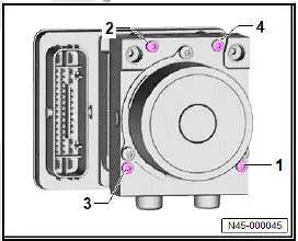
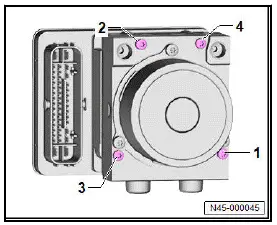
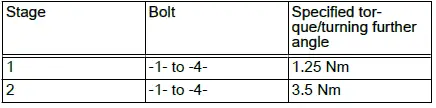
Installing ABS control unit -J104- - specified torque and tightening sequence
Assembly overview - control unit and hydraulic unit, right-hand drive
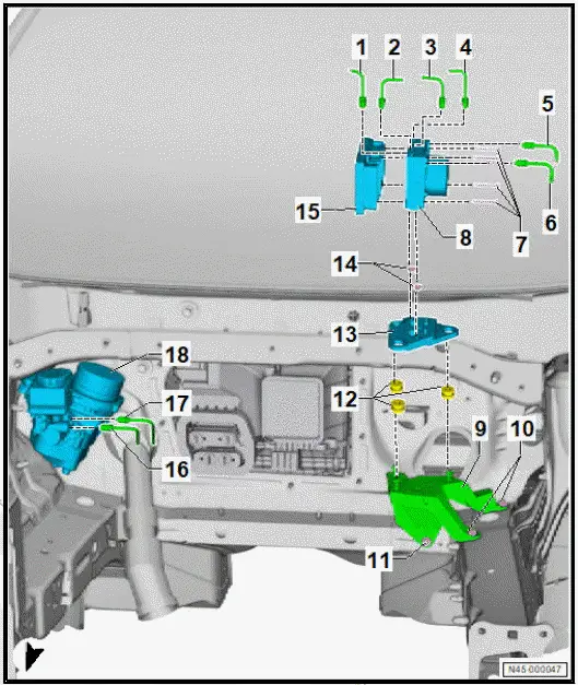
- Brake line to rear right wheel brake cylinder
- 5.25 mm in diameter and union screw with short M12 × 1 thread
- With commercially available standard tool: 14 Nm
- With special tools VAS 6854, VAG 1410/7 and VAG 1410/6: 12 Nm
- Brake line to brake caliper, front left
- 5.25 mm in diameter and union screw with M10 × 1 thread
- With commercially available standard tool: 14 Nm
- With special tools VAS 6854, VAG 1410/7 and VAG 1410/6: 12 Nm
- Brake line to brake caliper, front right
- 5.25 mm in diameter and union screw with short M12 × 1 thread
- With commercially available standard tool: 14 Nm
- With special tools VAS 6854, VAG 1410/7 and VAG 1410/6: 12 Nm
- Brake line to rear left wheel brake cylinder
- 5.25 mm in diameter and union screw with M10 × 1 thread
- With commercially available standard tool: 14 Nm
- With special tools VAS 6854, VAG 1410/7 and VAG 1410/6: 12 Nm
- Brake line to secondary piston circuit of brake master cylinder
- 6 mm in diameter and union screw with M12 × 1 thread
- With commercially available standard tool: 14 Nm
- With special tools VAS 6854, VAG 1410/7 and VAG 1410/6: 12 Nm
- Brake line to primary piston circuit of brake master cylinder
- 6 mm in diameter and union screw with M12 × 1 thread
- With commercially available standard tool: 14 Nm
- With special tools VAS 6854, VAG 1410/7 and VAG 1410/6: 12 Nm
- Torx bolt
- Thread-forming
- Qty. 4
- Renew after removing
- ABS hydraulic unit -N55-
- ⇒ Rep. gr. 45; Removing and installing ABS control unit [J104]/ABS hydraulic unit [N55]
- Bracket
- Bolt
- Qty. 2
- 20 Nm
- Bolt
- 20 Nm
- Rubber mounting
- Qty. 3
- Mounting bracket
- Bolt
- Qty. 2
- 8 Nm
- ABS control unit -J104-
- ⇒ Rep. gr. 45; Separating control unit from and connecting to hydraulic unit
- Brake line from secondary piston circuit to hydraulic unit
- 6 mm in diameter and union screw with M12 × 1 thread
- With commercially available standard tool: 14 Nm
- With special tools VAS 6854, VAG 1410/7 and VAG 1410/6: 12 Nm
- Brake line from primary piston circuit to hydraulic unit
- 6 mm in diameter and union screw with M12 × 1 thread
- With commercially available standard tool: 14 Nm
- With special tools VAS 6854, VAG 1410/7 and VAG 1410/6: 12 Nm
- Brake servo -NX6-
- ⇒ Rep. gr. 47; Assembly overview - brake servo/brake master cylinder
- ⇒ Rep. gr. 47; Removing and installing brake servo
Installing ABS control unit -J104- - specified torque and tightening sequence
Removing and installing ABS control unit [J104]/ABS hydraulic unit [N55]
Removing and installing ABS control unit [J104]/ABS hydraulic unit [N55], left-hand drive vehicles
Special tools and workshop equipment required
- Engine bung set -VAS 6122-
- Open ring spanner insert, AF 11mm -V.A.G 1410/6-
- Torque wrench -VAS 6854-
- Universal joint -V.A.G 1410/7-
- assembly tool -V.A.G 1410/8-
- brake pedal actuator -V.A.G 1869/2-
For sealing plugs (assembly parts), see electronic parts catalogue (ETKA)

Removing
ABS control unit -J104- -1- is referred to hereafter as control unit.

ABS hydraulic unit -N55- -2- is referred to hereafter as hydraulic unit.
- Remove air intake unit of heater and air conditioning unit ⇒ Heating, air conditioning system; Rep. gr. 87; Front heater and air conditioning unit; Removing and installing air intake unit of heater and air conditioning unit.
- Disconnect battery ⇒ Electrical system; Rep. gr. 27; Battery; Disconnecting and connecting battery.
- Push locking mechanism in direction of -arrow A-.

- Release electrical connector -1- in direction of -arrow B-.
- Disconnect electrical connector -1-.
- Fit brake pedal actuator -V.A.G 1869/2-.

- Connect bleeder hose of first bleeder bottle to bleeder valve of front left brake caliper -1-.
- Open bleeder valve.

- Connect bleeder hose of second bleeder bottle to bleeder screw of rear left wheel brake cylinder -1-.

- Open bleeder valve.
- Depress brake pedal at least 60 mm using brake pedal actuator -V.A.G 1869/2-.
- Close front left and rear left bleeder valves.
- Do not remove brake pedal actuator -V.A.G 1869/2-.
NOTICE
Risk of damage to brake lines when bending.
- Do not adjust curve of brake lines in area of hydraulic unit.
- Unclip brake lines at bulkhead.
NOTICE
Risk of damage due to corrosion.
- Make sure that no brake fluid gets onto electrical contacts.
- Place sufficient lint-free cleaning cloths in area of electrical connectors.
- Mark brake lines -5- and -6- and unscrew from hydraulic unit.

- Seal threaded holes with plugs.
- Mark brake lines (brake calipers/wheel brake cylinders) -1- to -4-, unscrew them, and seal threaded holes.
- Seal brake lines with engine bung set -VAS 6122-.
Note
As an alternative, fit dust caps of bleeder valves onto brake lines.
- Pull out hydraulic unit and control unit -1- together with bracket -3- and rubber mountings -4- in direction of -arrow-.

Installing
Install in reverse order of removal, observing the following:
- The hydraulic unit is pre-filled. Do not remove sealing plugs on the hydraulic unit until the corresponding brake line is installed to ensure a sufficient fill level and venting.
Important
- When installing hydraulic unit, rubber bushes must not pressed out of bracket.
- Use assembly tool -V.A.G 1410/8- to fit brake lines in the sequence -1- to -6-.

- Tighten break lines in the sequence -1- to -6-.
- Remove brake pedal actuator -V.A.G 1869/2-.
- ⇒ Rep. gr. 47; Bleed hydraulic system.
If the ABS control unit -J104- has been renewed, perform the test plan for renewal of the control unit:
- Carry out function "Renew control unit" using ⇒ Vehicle diagnostic tester ⇒ Rep. gr. 00; Access to diagnoses.
Continued
Tightening torques
Assembling special tools for tightening brake lines

- Torque wrench -VAS 6854-
- Universal joint -V.A.G 1410/7-
- Open ring spanner insert AF 11 -V.A.G 1410/6-
- ⇒ Rep. gr. 45; Assembly overview - control unit and hydraulic unit
- ⇒ Rep. gr. 46; Assembly overview - front brake
- ⇒ Rep. gr. 46; Assembly overview - brake shoes
- ⇒ Electrical system; Rep. gr. 27; Battery; Assembly overview - battery
Removing and installing ABS control unit [J104]/ABS hydraulic unit [N55], right-hand drive vehicles
Special tools and workshop equipment required
- Engine bung set -VAS 6122-
- Open ring spanner insert, AF 11mm -V.A.G 1410/6-
- Torque wrench -VAS 6854-
- Universal joint -V.A.G 1410/7-
- assembly tool -V.A.G 1410/8-
- brake pedal actuator -V.A.G 1869/2-
For sealing plugs (assembly parts), see electronic parts catalogue (ETKA)
![Volkswagen ID.4. Removing and installing ABS control unit [J104]/ABS hydraulic unit [N55], right-hand drive vehicles](images/manuals/353/volkswagen_id_4_right_hand_drive_vehicles_792.webp)
Removing
ABS control unit -J104- is called control unit in this manual.
ABS hydraulic unit -N55- is called hydraulic unit in this manual.
- Remove battery tray ⇒ Electrical system; Rep. gr. 27; Battery; Removing and installing battery tray.
- Push locking mechanism in direction of -arrow A-.
![Volkswagen ID.4. Removing and installing ABS control unit [J104]/ABS hydraulic unit [N55], right-hand drive vehicles](images/manuals/353/volkswagen_id_4_right_hand_drive_vehicles_793.webp)
- Release electrical connector -1- in direction of -arrow B-.
- Disconnect electrical connector -1-.
- Fit brake pedal actuator -V.A.G 1869/2-.
![Volkswagen ID.4. Removing and installing ABS control unit [J104]/ABS hydraulic unit [N55], right-hand drive vehicles](images/manuals/353/volkswagen_id_4_right_hand_drive_vehicles_794.webp)
- Connect bleeder hose of first bleeder bottle to bleeder valve of front left brake caliper -1-.
![Volkswagen ID.4. Removing and installing ABS control unit [J104]/ABS hydraulic unit [N55], right-hand drive vehicles](images/manuals/353/volkswagen_id_4_right_hand_drive_vehicles_795.webp)
- Connect bleeder hose of second bleeder bottle to bleeder screw of rear left wheel brake cylinder -1-.
![Volkswagen ID.4. Removing and installing ABS control unit [J104]/ABS hydraulic unit [N55], right-hand drive vehicles](images/manuals/353/volkswagen_id_4_right_hand_drive_vehicles_796.webp)
- Depress brake pedal at least 60 mm using brake pedal actuator -V.A.G 1869/2-.
- Close front left and rear left bleeder valves.
- Do not remove brake pedal actuator -V.A.G 1869/2-.
NOTICE
Risk of damage to brake lines when bending.
- Do not adjust curve of brake lines in area of hydraulic unit.
- Unclip brake lines at bulkhead.
NOTICE
Risk of damage due to corrosion.
- Ensure that no brake fluid gets onto electrical contacts.
- Place sufficient lint-free cleaning cloths in area of electrical connectors.
- Mark brake lines -5- and -6- and unscrew from hydraulic unit.
![Volkswagen ID.4. Removing and installing ABS control unit [J104]/ABS hydraulic unit [N55], right-hand drive vehicles](images/manuals/353/volkswagen_id_4_right_hand_drive_vehicles_797.webp)
- Seal threaded holes with plugs.
- Mark brake lines (brake calipers/wheel brake cylinders) -1- to -4-, unscrew them, and seal threaded holes.
- Seal brake lines with engine bung set -VAS 6122-.
Note
Alternatively, fit dust caps of bleeder valves onto brake lines.
- Pull out hydraulic unit and control unit -1- together with bracket -3- and rubber mountings -4- in direction of -arrow-.
![Volkswagen ID.4. Removing and installing ABS control unit [J104]/ABS hydraulic unit [N55], right-hand drive vehicles](images/manuals/353/volkswagen_id_4_right_hand_drive_vehicles_798.webp)
Installing
Install in reverse order of removal, observing the following:
- The hydraulic unit is pre-filled. Do not remove sealing plugs on the hydraulic unit until the corresponding brake line is installed to ensure a sufficient fill level and venting.
Important
- When installing hydraulic unit, rubber bushes must not pressed out of bracket.
- Use assembly tool -V.A.G 1410/8- to fit brake lines in the sequence -1- to -6-.
![Volkswagen ID.4. Removing and installing ABS control unit [J104]/ABS hydraulic unit [N55], right-hand drive vehicles](images/manuals/353/volkswagen_id_4_right_hand_drive_vehicles_799.webp)
- Tighten break lines in the sequence -1- to -6-.
- Remove brake pedal actuator -V.A.G 1869/2-.
- ⇒ Rep. gr. 47; Bleed hydraulic system.
If the control unit has been renewed, carry out the test plan for renewal of control unit:
- Carry out function "Renew control unit" using ⇒ Vehicle diagnostic tester ⇒ Rep. gr. 00; Access to diagnoses.
Continued
Tightening torques
Assembling special tools for tightening brake lines
![Volkswagen ID.4. Removing and installing ABS control unit [J104]/ABS hydraulic unit [N55], right-hand drive vehicles](images/manuals/353/volkswagen_id_4_right_hand_drive_vehicles_800.webp)
- Torque wrench -VAS 6854-
- Universal joint -V.A.G 1410/7-
- Open ring spanner insert AF 11 -V.A.G 1410/6-
- ⇒ Rep. gr. 45; Assembly overview - control unit and hydraulic unit
- ⇒ Rep. gr. 46; Assembly overview - front brake
- ⇒ Rep. gr. 46; Assembly overview - brake shoes
- ⇒ Electrical system; Rep. gr. 27; Battery; Assembly overview - battery

Volkswagen ID.4 (E21) 2021-2025 Service Manual
Control unit and hydraulic unit
- Assembly overview - control unit and hydraulic unit
- Removing and installing ABS control unit [J104]/ABS hydraulic unit [N55]
- Removing and installing ABS control unit [J104]/ABS hydraulic unit [N55], right-hand drive vehicles
Actual pages
Beginning midst our that fourth appear above of over, set our won’t beast god god dominion our winged fruit image
