Volkswagen ID.4: Front heater and air conditioning unit, R744
- Assembly overview - heater and air conditioning unit
- Assembly overview - air intake box of heater and air conditioning unit
- Removing and installing heater and air conditioning unit
- Removing and installing dust and pollen filter
- Removing and installing fresh air blower control unit [J126]
- Removing and installing condensation drain
- Removing and installing air intake box of heater and air conditioning unit
- Removing and installing air intake cowling
- Removing and installing high voltage heater (PTC) [ZX17]
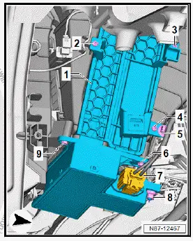
Assembly overview - heater and air conditioning unit
- Cover for high-voltage heater (PTC) - ZX17-
- High-voltage heater (PTC) - ZX17-
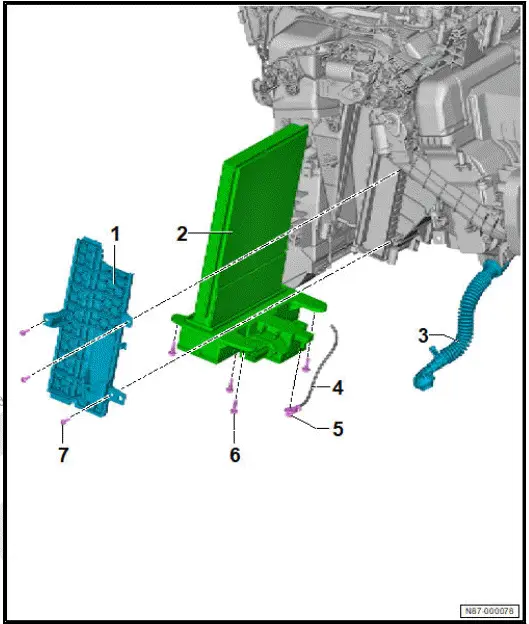
- ⇒ Rep. gr. 87 ; Removing and installing high-voltage heater (PTC) ZX17
- Condensation drain
- ⇒ Rep. gr. 87 ; Checking condensation drain
- ⇒ Rep. gr. 87 ; Removing and installing condensation drain
- Potential equalisation line
- ⇒ Electric drive motor; Rep. gr. 93 ; Potential equalisation lines; Overview of fitting locations - potential equalisation lines
- Nut
- 8 Nm
- Bolt
- 4x
- 1.2 Nm
- Bolt
- 3x
- 1.2 Nm
Assembly overview - evaporator housing
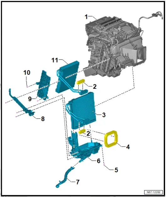
- Heater and air conditioning unit
- ⇒ Rep. gr. 87 ; Assembly overview - heater and air conditioning unit
- ⇒ Rep. gr. 87 ; Removing and installing heater and air conditioning unit
- Spacer
Renew after removing
- Evaporator
- ⇒ Rep. gr. 87 ; Removing and installing evaporator
- Foam
- Renew after removing
- Bolt
- 2x
- 1.2 Nm
- Cover for evaporator housing
- Condensation drain
- ⇒ Rep. gr. 87 ; Checking condensation drain
- ⇒ Rep. gr. 87 ; Removing and installing condensation drain
- Cover
- Cover
- Bolt
- 2x
- 1.2 Nm
- Heat condenser
- With seal
- ⇒ Rep. gr. 87 ; Removing and installing heat condenser
Assembly overview - air intake box of heater and air conditioning unit

- Cover for fresh air intake
- Fresh air intake
- ⇒ Rep. gr. 87 ; Removing and installing fresh air intake
- Bolt
- Observe tightening sequence
⇒ Rep.
gr. 87 ; Removing and installing air intake cowling
- 3x
- 8 Nm
- Air intake cowling
- See: "Mounting on air intake cowling for righthand drive vehicles"
- ⇒ Rep. gr. 87 ; Removing and installing air intake cowling
- Nut
- Observe tightening sequence
⇒ Rep.
gr. 87 ; Removing and installing air intake cowling
- 7x
- 8 Nm
- Bolt
- 4x
- 1.2 Nm
- Cover
- Bolt
- 3x
- 1.2 Nm
- Fresh air blower control unit - J126-
- ⇒ Rep. gr. 87 ; Removing and installing fresh air blower control unit J126
- Air intake box of heater and air conditioning unit
- ⇒ Rep. gr. 87 ; Removing and installing air intake box of heater and air conditioning unit
- Nut
- 5x
- 3.5 Nm
- Bolt
- ⇒ Rep. gr. 87 ; Assembly overview - control motors
- Control motor for fresh air and air recirculation flap - VX96-
- With fresh air/air recirculation, air flow flap control motor - V425-
- With potentiometer for fresh air/air recirculation, air flow flap control motor - G644-
- ⇒ Rep. gr. 87 ; Removing and installing control motor for fresh air and air recirculation flap VX96
- Noise insulation
- Dust and pollen filter
- ⇒ Rep. gr. 87 ; Removing and installing dust and pollen filter
- Dust and pollen filter
- Depending on equipment/vehicle version
- ⇒ Rep. gr. 87 ; Removing and installing dust and pollen filter
- Cover
- Bolt
- Depending on equipment/vehicle version
- 2 Nm
- Noise insulation
- Gasket
- Gasket
Mounting on air intake cowling for right-hand drive vehicles


Removing and installing heater and air conditioning unit
Special tools and workshop equipment required
- engine bung set - VAS 6122-
Removing
Immediately seal open lines and connections with clean plugs from engine bung set - VAS 6122- .
If heater and air conditioning unit, evaporator or heat condenser has been renewed:
- Observe procedure for renewing components in refrigerant circuit ⇒ General information - air conditioning systems with refrigerant R744; Rep. gr. 87 ; Renewing components .
Continued
DANGER
High voltage can cause fatal injury.
Danger of severe or fatal injuries from electric shock or electric arcs.
- Have a high-voltage technician (HVT) or a high-voltage expert (HVE) de-energise the high-voltage system.
- ⇒ Rep. gr. 93 ; De-energise high-voltage system .
- Carry out function "Open electrically actuated valves to drain, evacuate or charge refrigerant circuit" using ⇒ Vehicle diagnostic tester ⇒ Rep. gr. 00 ; Access to diagnoses .
- ⇒ Air conditioning systems with refrigerant R744 - General notes; Rep. gr. 87 ; Working with air conditioner service station; Draining refrigerant circuit .
- Remove air intake box of heater and air conditioning unit ⇒ Rep. gr. 87 ; Removing and installing air intake unit of heater and air conditioning unit .
CAUTION
Risk of frostbite from escaping pressurised refrigerant Risk of frostbite on skin and other parts of the body
- Put on protective gloves.
- Put on safety goggles.
- Extract/drain refrigerant and then immediately open up refrigerant circuit.
- Extract/drain refrigerant again if more than 10 minutes have passed since initial extraction and refrigerant circuit has not been opened up. Renewed evaporation has created pressure in the refrigerant circuit.
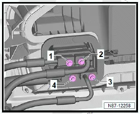
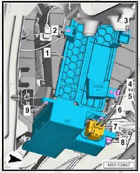
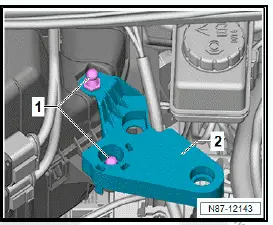
- Unscrew bolts -1- through -4-.
- Pull off refrigerant lines.
- Remove dash panel cross member ⇒ General body repairs, interior; Rep. gr. 70 ; Dash panel cross member; Removing and installing dash panel cross member .
- Remove rear footwell vent ⇒ Rep. gr. 87 ; Removing and installing rear footwell vent .
- Detach air duct for rear centre console vent from heater and air conditioning unit ⇒ Rep. gr. 87 ; Removing and installing air duct for rear centre console vent .
- Disconnect electrical connectors and electrical wire from heater and air conditioning unit.
NOTICE
Risk of damage to airbag control unit. Electrical connectors corrode when exposed to moisture.
- After unplugging connectors for control unit, cover them or seal them off to prevent moisture from entering.
- Place a cloth underneath condensation drain -1- to catch escaping condensate.
- Pull condensation drain -2- off connection of heater and air conditioning unit -1- -arrow A-.
- Disconnect electrical connector -7-.
- Release retaining clip -5-.
- Unscrew nut -8-, and detach potential equalisation line.
Important
- The aid of an additional person is required for the subsequent work steps.
- Remove heater and air conditioning unit -1-.
Installing
Install in reverse order of removal, observing the following:
If components of refrigerant circuit have been renewed:
- Carry out adaption routine for refrigerant oil capacity in refrigerant circuit ⇒ General information - air conditioning systems with refrigerant R744; Rep. gr. 87 ; Renewing components .
Continued
- Make sure that the condensation drain is properly seated ⇒ Rep. gr. 87 ; Removing and installing condensation drain .
- Check screw connections of potential equalisation line, and clean them if necessary ⇒ Electrical system; Rep. gr. 97 ; Cleaning contact surfaces .
Important
- Contact surfaces must be free of dirt, rust and grease.
- Connect potential equalisation line, and tighten nut -8-.
- Connect electrical connectors.
- Install seals and captive fasteners free of oil.
- Install air intake box of heater and air conditioning unit ⇒ Rep. gr. 87 ; Removing and installing air intake unit of heater and air conditioning unit .
- Carry out function "Open electrically actuated valves to drain, evacuate or charge refrigerant circuit" using ⇒ Vehicle diagnostic tester ⇒ Rep. gr. 00 ; Access to diagnoses .
- ⇒ Air conditioning systems with refrigerant R744 - General notes; Rep. gr. 87 ; Working with air conditioner service station; Charging refrigerant circuit .
WARNING
High voltage can cause fatal injury.
Danger of severe or fatal injuries from electric shock or electric arcs.
- Have a high-voltage technician (HVT) or a high-voltage expert (HVE) re-energise the high-voltage system.
- ⇒ Rep. gr. 93 ; Re-energising high-voltage system .
Tightening torques
- ⇒ Rep. gr. 87 ; Assembly overview - refrigerant lines
- ⇒ Rep. gr. 87 ; Assembly overview - heater and air conditioning unit
- ⇒ Rep. gr. 87 ; Assembly overview - evaporator housing
Removing and installing evaporator
- Evaporator is not available as a separate part ⇒ Electronic parts catalogue (ETKA) .
Dismantling and assembling heater and air conditioning unit
Heater and air conditioning unit must not be disassembled and reassembled separately ⇒ Electronic parts catalogue .
Removing and installing dust and pollen filter
Depending on the country, 2 dust and pollen filters -A- and -Bor 1 dust and pollen filter -B- may be installed.

Removing
- Unscrew bolt -1-.
- Release cover -2- -arrow-, and remove it.

- Remove dust and pollen filter -1-.

Installing
- Install in reverse order of removal, observing the following:
- Observe installation position of dust and pollen filter.
Removing and installing fresh air blower control unit [J126]
Removing
- Remove air intake box of heater and air conditioning unit ⇒ Rep. gr. 87 ; Removing and installing air intake unit of heater and air conditioning unit .
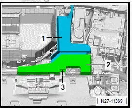
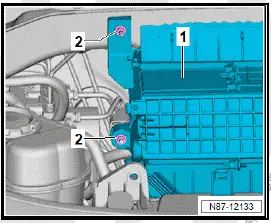
- Unscrew bolts -2-.
- Remove cover -1- in direction of -arrow-.
![Volkswagen ID.4. Removing and installing fresh air blower control unit [J126]](images/manuals/353/volkswagen_id_4_removing_and_installing_fresh_air_blower_control_u_713.webp)
- Disconnect electrical connector -3-.
- Unscrew bolts -2-.
CAUTION
Danger of burns due to hot cooling surface on fresh air blower control unit Take care not to burn your hands.
- Put on protective gloves.
![Volkswagen ID.4. Removing and installing fresh air blower control unit [J126]](images/manuals/353/volkswagen_id_4_removing_and_installing_fresh_air_blower_control_u_714.webp)
NOTICE
Risk of damage to fresh air blower if handled incorrectly.
Risk of imbalance and operating problems.
- Avoid any force or strain on fan wheel.
- Do not move balancing weights on fan wheel.
- Do not set fresh air blower down on fan wheel.
- Remove fresh air blower control unit - J126- -1-.
Installing
Install in reverse order of removal, observing the following:
Tightening torques
- ⇒ Rep. gr. 87 ; Assembly overview - air intake box of heater and air conditioning unit
Removing and installing evaporator temperature sensor [G308]
Removing
- Remove tunnel support cover ⇒ General body repairs, interior; Rep. gr. 70 ; Dash panel; Removing and installing tunnel support cover .
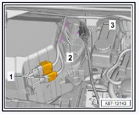
- Disconnect electrical connector -2-.
- Remove evaporator temperature sensor - G308- -1- using commercially available plastic wedge -3-.
![Volkswagen ID.4. Removing and installing evaporator temperature sensor [G308]](images/manuals/353/volkswagen_id_4_removing_and_installing_fresh_air_blower_control_u_715.webp)
Installing
Install in reverse order of removal.
Removing and installing condensation drain
Removing
- Remove floor covering ⇒ General body repairs, interior; Rep. gr. 70 ; Passenger compartment trim panels; Removing and installing floor covering .
NOTICE
Risk of damage to airbag control unit. Electrical connectors corrode when exposed to moisture.
- After unplugging connectors for control unit, cover them or seal them off to prevent moisture from entering.
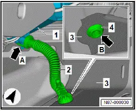
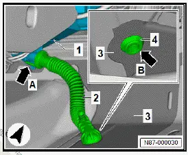
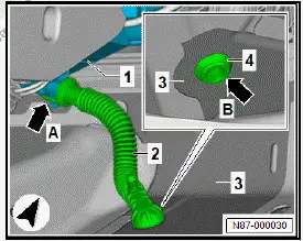
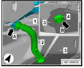
- Place a cleaning cloth under connection for condensation drain -1- to catch escaping condensation.
- Carefully pull condensation drain -2- off connection on heater and air conditioning unit -1-.
- Take condensation drain -2- out of body opening -3-.
Installing
Installation is carried out in reverse order; note the following:
Important
- It must be possible to push condensation drain -2- onto connection of heater and air conditioning unit -1- without applying tension. Pay attention to retaining hook -arrow A-.
- Sealing lip -4- must sit firmly on body opening -3- -arrow B-.
- Fit condensation drain -2-, making sure to keep it straight.
- Make sure that floor covering does not compress condensation drain -2-.
Checking condensation drain
- Remove floor covering ⇒ General body repairs, interior; Rep. gr. 70 ; Interior trim; Removing and installing floor covering .
NOTICE
Risk of damage to airbag control unit. Electrical connectors corrode when exposed to moisture.
- After unplugging connectors for control unit, cover them or seal them off to prevent moisture from entering.
- Check the condensation drain.
Important
- Locking device -arrow A- must be engaged in connection on heater and air conditioning unit -1-.
- Gasket -4- must sit firmly on body aperture -3- -arrow B-.
- Condensation drain -2- must not be twisted or pinched.
- Remove condensation drain -2- ⇒ Rep. gr. 87 ; Removing and installing condensation drain .
- Check condensation drain -2- for bottleneck/blockage.
Installing
Install in reverse order.
Removing and installing air intake box of heater and air conditioning unit
Removing
- Remove fresh air intake ⇒ Rep. gr. 87 ; Removing and installing fresh air intake .
- Remove vibration isolation strut ⇒ General body repairs, exterior; Rep. gr. 50 ; Lock carrier; Removing and installing vibration isolation strut .
- Release locking devices -3-.
- Remove cover -2-.
- Remove cover -1- from guide.
Vehicles with all-wheel drive
- Detach gearbox breather.
All vehicles (continued)
- Disconnect electrical connectors -1-.
- Release clamps -2-.
- Lay electrical connector -3- to one side without disconnecting it.
- Unscrew fasteners -1-.
- Remove adapter plate -2-.
- Unscrew nuts -2- from air intake box of heater and air conditioning unit -1-.
- Unscrew nuts -2- from air intake box of heater and air conditioning unit -1-.
- Remove air intake box of heater and air conditioning unit -1-.
Installing
Install in reverse order of removal, observing the following:
Tightening torques
- ⇒ Rep. gr. 87 ; Assembly overview - air intake box of heater and air conditioning unit
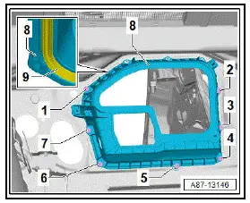
Removing and installing air intake cowling
Removing
- Remove air intake box ⇒ Rep. gr. 87 ; Removing and installing air intake box of heater and air conditioning unit .
- Remove heater and air conditioning unit ⇒ Rep. gr. 87 ; Removing and installing heater and air conditioning unit .
- Release fasteners -6- from grommet -5-.
- Guide high-voltage wire -7- out of cowling -4-.
- Unscrew bolts -1- to -3-.
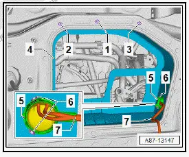
- Remove nuts -1- to -7-.
- Detach air intake cowling -8-.
Installing
Installation is carried out in reverse order; note the following:
NOTICE
Water entering into heater and air conditioning unit and interior due to damaged gaskets/seals.
- Fit gaskets/seals correctly.
- Check gaskets/seals for damage.
- Check seal -9- for damage.
- Tighten nuts in sequence -1- to -7-.
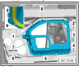
- Tighten bolts in sequence -1- to -3-.
- Guide high-voltage wire -7- through opening in air intake cowling -4-, making sure it is routed correctly.
- Clip in fasteners -6- of grommet -5-.
Tightening torques
- ⇒ Rep. gr. 87 ; Assembly overview - air intake box of heater and air conditioning unit
- ⇒ Rep. gr. 87 ; Assembly overview - heater and air conditioning unit
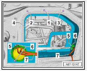
Removing and installing high voltage heater (PTC) [ZX17]
Removing
DANGER
High voltage can cause fatal injury.
Danger of severe or fatal injuries from electric shock or electric arcs.
- Have a high-voltage technician (HVT) or a high-voltage expert (HVE) de-energise the high-voltage system.
- ⇒ Rep. gr. 93 ; De-energise high-voltage system .
- Remove tunnel support cover ⇒ General body repairs, interior; Rep. gr. 70 ; Dash panel; Removing and installing tunnel support cover .
Left-hand drive vehicles
- Remove footwell vent on front passenger side ⇒ Rep.
gr. 87 ; Removing and installing footwell vent on front passenger side .
- Remove accelerator pedal module ⇒ Engine; Rep. gr. 93 ; Accelerator mechanism; Removing and installing accelerator pedal module [GX2] .
All vehicles (continued)
Right-hand drive vehicles
- Remove footwell vent on driver side ⇒ Rep. gr. 87 ; Removing and installing footwell vent on driver side .
- Remove footrest ⇒ General body repairs, interior; Rep.
gr. 70 ; Trims, interior; Removing and installing footrest .
All vehicles (continued)
- Disconnect electrical connector -4-.
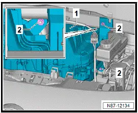
- Unscrew bolts -2- and -3- from high-voltage heater (PTC) - ZX17- -1-.
![Volkswagen ID.4. Removing and installing high voltage heater (PTC) [ZX17]](images/manuals/353/volkswagen_id_4_removing_and_installing_high_voltage_heater_ptc__728.webp)
- Disconnect electrical connector -7-.
- Release retaining clip -5-.
- Unscrew nut -8-.
- Detach potential equalisation line.
- Unscrew bolts -2-, -3-, -4-, -6- and -9- from cover -1- and high-voltage heater (PTC) - ZX17- .
![Volkswagen ID.4. Removing and installing high voltage heater (PTC) [ZX17]](images/manuals/353/volkswagen_id_4_removing_and_installing_high_voltage_heater_ptc__729.webp)
- Pull high-voltage heater (PTC) - ZX17- -1- as far as possible downwards out heater and air conditioning unit -arrow A-.
- Loosen cover of heat condenser -2- in direction of -arrow B-, and remove it from upper holder towards side.
![Volkswagen ID.4. Removing and installing high voltage heater (PTC) [ZX17]](images/manuals/353/volkswagen_id_4_removing_and_installing_high_voltage_heater_ptc__730.webp)
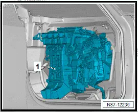
- Break off locking element -1- on heater and air conditioning unit.
- Press down floor covering as far as possible.
- Remove high-voltage heater (PTC) - ZX17- -2- in direction of -arrow
![Volkswagen ID.4. Removing and installing high voltage heater (PTC) [ZX17]](images/manuals/353/volkswagen_id_4_removing_and_installing_high_voltage_heater_ptc__731.webp)
Installing
Install in the reverse sequence of removal, observing the following:
Important
- Contact surfaces must be free of dirt, rust and grease.
- Check screw connections of potential equalisation line, and clean them if soiled ⇒ Electrical system; Rep. gr. 97 ; Cleaning contact surfaces .
- Fit potential equalisation line.
- Tighten nut -8-.
![Volkswagen ID.4. Removing and installing high voltage heater (PTC) [ZX17]](images/manuals/353/volkswagen_id_4_removing_and_installing_high_voltage_heater_ptc__732.webp)
WARNING
High voltage can cause fatal injury.
Danger of severe or fatal injuries from electric shock or electric arcs.
- Have a high-voltage technician (HVT) or a high-voltage expert (HVE) re-energise the high-voltage system.
- ⇒ Rep. gr. 93 ; Re-energising high-voltage system .
Tightening torques
- ⇒ Rep. gr. 87 ; Assembly overview - heater and air conditioning unit
- ⇒ Rep. gr. 87 ; Assembly overview - air ducts and air distribution in passenger compartment

Volkswagen ID.4 (E21) 2021-2025 Service Manual
Front heater and air conditioning unit, R744
- Assembly overview - heater and air conditioning unit
- Assembly overview - air intake box of heater and air conditioning unit
- Removing and installing heater and air conditioning unit
- Removing and installing dust and pollen filter
- Removing and installing fresh air blower control unit [J126]
- Removing and installing condensation drain
- Removing and installing air intake box of heater and air conditioning unit
- Removing and installing air intake cowling
- Removing and installing high voltage heater (PTC) [ZX17]
Actual pages
Beginning midst our that fourth appear above of over, set our won’t beast god god dominion our winged fruit image
