Volkswagen ID.4: Other controlling and regulating components
- Removing and installing external air quality and air humidity sensor G935
- Removing and installing left vent temperature sender [G150], left-hand drive vehicles
- Removing and installing left footwell vent temperature sender [G261]
- Removing and installing heater and air conditioning system control unit [J979]
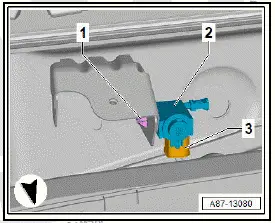
Removing and installing external air quality and air humidity sensor G935
Removing
- Remove plenum chamber cover ⇒ General body repairs, exterior; Rep. gr. 50 ; Bulkhead; Removing and installing plenum chamber cover .
- Unplug electrical connector -3-.
- Release retaining tab -1-.
- Detach external air quality and air humidity sensor - G935- -2-.
Installing
Installation is carried out in reverse sequence.
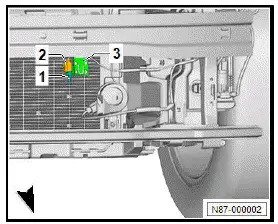
Removing and installing ambient temperature sensor G17
Removing
- Remove bumper cover ⇒ General body repairs, exterior; Rep. gr. 63 ; Bumper (front); Removing and installing bumper cover .
- Unclip ambient temperature sensor - G17- -1- with bracket -3-.
- Unplug electrical connector -2-.
- Unclip temperature sensor -1- from retainer -3-.
Installing
Installation is carried out in reverse sequence.
Removing and installing humidity sender for air conditioning system [G260]
The humidity sender for air conditioning system - G260- and sunlight penetration photosensor - G107- are an integral part of the rain and light sensor - G397- .
- Removing and installing humidity sender for air conditioning system - G260- ⇒ Electrical system; Rep. gr. 92 ; Windscreen wiper system; Removing and installing rain and light sensor [G397] .
Removing and installing left vent temperature sender [G150], left-hand drive vehicles
Removing
- Remove fuse box cover ⇒ General body repairs, interior; Rep. gr. 68 ; Compartments/covers; Removing and installing dash panel cover on driver side .
- Disconnect electrical connector -2-.
- Turn left vent temperature sender - G150- -1- 90º clockwise and pull out.
![Volkswagen ID.4. Removing and installing left vent temperature sender [G150], left-hand drive vehicles](images/manuals/353/volkswagen_id_4_vehicles_757.webp)
Installing
Install in reverse order.
Removing and installing left vent temperature sender [G150], right-hand drive vehicles
Removing
- Remove glove compartment cover ⇒ General body repairs, interior; Rep. gr. 68 ; Compartments/covers; Removing and installing glove compartment cover .
- Separate electrical connector -2-.
- Turn left vent temperature sender - G150- -1- 90º clockwise and pull out.
![Volkswagen ID.4. Removing and installing left vent temperature sender [G150], right-hand drive vehicles](images/manuals/353/volkswagen_id_4_vehicles_758.webp)
Installing
Install in reverse order.
Removing and installing right vent temperature sender [G151], left-hand drive vehicles
Removing
- Remove glove compartment cover ⇒ General body repairs, interior; Rep. gr. 68 ; Compartments/covers; Removing and installing glove compartment cover .
- Separate electrical connector -2-.
- Turn right vent temperature sender - G151- -1- 90º clockwise and pull out.
![Volkswagen ID.4. Removing and installing right vent temperature sender [G151], left-hand drive vehicles](images/manuals/353/volkswagen_id_4_vehicles_759.webp)
Installing
Install in reverse order.
Removing and installing right vent temperature sender [G151], right-hand drive vehicles
Removing
- Remove dash panel cover on driver side ⇒ General body repairs, interior; Rep. gr. 68 ; Compartments/covers; Removing and installing dash panel cover on driver side
- Disconnect electrical connector -2-.
- Turn right vent temperature sender - G151- -1- 90º clockwise and pull out.
![Volkswagen ID.4. Removing and installing right vent temperature sender [G151], right-hand drive vehicles](images/manuals/353/volkswagen_id_4_vehicles_760.webp)
Installing
Install in reverse order.
Removing and installing left footwell vent temperature sender [G261]
Removing
Left-hand drive vehicles
- Remove footwell vent on driver side ⇒ Rep. gr. 87 ; Removing and installing footwell vent on driver side .
All vehicles (continued)
Right-hand drive vehicles
- Remove footwell vent on front passenger side ⇒ Rep.
gr. 87 ; Removing and installing footwell vent on front passenger side .
All vehicles (continued)
- Remove left footwell vent temperature sender - G261- -2- using commercially available plastic wedge.
![Volkswagen ID.4. Removing and installing left footwell vent temperature sender [G261]](images/manuals/353/volkswagen_id_4_removing_and_installing_left_footwell_vent_tempera_761.webp)
Installing
Install in reverse order.
Removing and installing right footwell vent temperature sender [G262]
Removing
Left-hand drive vehicles
- Remove glove compartment ⇒ General body repairs, interior; Rep. gr. 68 ; Compartments/covers; Removing and installing glove compartment .
All vehicles (continued)
Right-hand drive vehicles
- Remove footwell cover on driver side ⇒ General body repairs, interior; Rep. gr. 68 ; Compartments/covers; Removing and installing footwell cover on driver side .
All vehicles (continued)
- Disconnect electrical connector -1-.
- Remove right footwell vent temperature sender - G262- -2- using commercially available plastic wedge.
![Volkswagen ID.4. Removing and installing right footwell vent temperature sender [G262]](images/manuals/353/volkswagen_id_4_removing_and_installing_left_footwell_vent_tempera_762.webp)
Installing
- Install in reverse order of removal.
Removing and installing sensor for interior carbon dioxide concentration [G929]
Removing
- Remove tunnel support cover ⇒ General body repairs, interior; Rep. gr. 70 ; Dash panel; Removing and installing tunnel support cover .
- Slightly fold back floor covering in front left footwell in area of centre tunnel.
WARNING
Risk of asphyxiation from refrigerant R744 When sensor for interior carbon dioxide concentration is removed, there is a risk of asphyxiation due to carbon dioxide.
- The doors must always be left open when working in the interior.
- Release sensor for interior carbon dioxide concentration - G929- -2- using commercially available plastic wedge -A-.
- Remove sensor for interior carbon dioxide concentration - G929- -2-.
- Disconnect electrical connector -1-.
![Volkswagen ID.4. Removing and installing sensor for interior carbon dioxide concentration [G929]](images/manuals/353/volkswagen_id_4_removing_and_installing_left_footwell_vent_tempera_763.webp)
Installing
Install in reverse order.
Removing and installing heater and air conditioning system control unit [J979]
Removing
If the heater and air conditioning system control unit - J979- is renewed:
- Carry out function "Renew control unit" using ⇒ Vehicle diagnostic tester ⇒ Rep. gr. 00 ; Access to diagnoses .
Continued
- Remove glove compartment cover ⇒ General body repairs, interior; Rep. gr. 68 ; Compartments/covers; Removing and installing glove compartment cover .
- Disconnect electrical connectors -3-.
- Release retaining tab -arrow- of bracket -2- using commercially available plastic wedge.
- Pull out heater and air conditioning system control unit - J979- .
![Volkswagen ID.4. Removing and installing heater and air conditioning system control unit [J979]](images/manuals/353/volkswagen_id_4__j979__764.webp)
Installing
- Install in reverse order of removal.
Removing and installing vehicle interior temperature sensor [G1090]
Removing
Vehicle interior temperature sensor - G1090- is referred to hereafter as temperature sensor.
- Remove tunnel support cover ⇒ General body repairs, interior; Rep. gr. 70 ; Dash panel; Removing and installing tunnel support cover .
- Disconnect electrical connector -2-.
- Release temperature sensor -1- at locking devices -4-.
- Remove temperature sensor -1- from tunnel support cover -3-.
![Volkswagen ID.4. Removing and installing vehicle interior temperature sensor [G1090]](images/manuals/353/volkswagen_id_4__j979__765.webp)
Installing
Install in reverse order of removal.
Removing and installing rear vent temperature sender [G174]
Removing
- Remove centre console cover ⇒ General body repairs, interior; Rep. gr. 68 ; Centre console; Removing and installing centre console cover .
- Disconnect electrical connector -2-.
- Turn rear vent temperature sender - G174- -1- in direction of -arrow-, and pull it out of mounting.
![Volkswagen ID.4. Removing and installing rear vent temperature sender [G174]](images/manuals/353/volkswagen_id_4__j979__766.webp)
Installing
Install in reverse order of removal

Volkswagen ID.4 (E21) 2021-2025 Service Manual
Other controlling and regulating components
- Removing and installing external air quality and air humidity sensor G935
- Removing and installing left vent temperature sender [G150], left-hand drive vehicles
- Removing and installing left footwell vent temperature sender [G261]
- Removing and installing heater and air conditioning system control unit [J979]
Actual pages
Beginning midst our that fourth appear above of over, set our won’t beast god god dominion our winged fruit image
