Volkswagen ID.4: Brake servo and brake master cylinder
- Assembly overview - brake servo/brake master cylinder
- Removing and installing brake master cylinder
- Removing and installing brake servo
- Removing and installing brake servo [NX6], right-hand drive vehicles
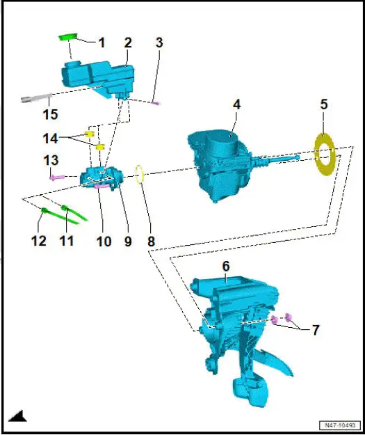
Assembly overview - brake servo/brake master cylinder
Assembly overview - brake servo/brake master cylinder, left-hand drive vehicles

- Brake line
- Brake master cylinder/ secondary piston circuit to hydraulic unit
- M12 x 1
- With standard tool: 14 Nm
- With special tools VAS 6854, VAG 1410/7 and VAG 1410/6: 12 Nm
- Brake line
- Brake master cylinder/ primary piston circuit to hydraulic unit
- M12 x 1
- With standard tool: 14 Nm
- With special tools VAS 6854, VAG 1410/7 and VAG 1410/6: 12 Nm
- Brake fluid level warning contact -F34-
- Cap
- Brake fluid reservoir
- Bolt
- 4 Nm
- Brake servo -NX6-
- With brake servo control unit -J539-
- With brake pedal position sender -G100-
- With brake pedal position sender 2 -G836-
- ⇒ Rep. gr. 47; Removing and installing brake servo
- Gasket for brake servo
- Renew after removing
- Nut
- Qty. 2
- Renew after removing
- 20 Nm
- Mounting bracket with brake pedal
- ⇒ Rep. gr. 46; Assembly overview - brake pedal
- ⇒ Rep. gr. 46; Removing and installing mounting bracket
- Seal
- Renew after removing
- Brake master cylinder
- ⇒ a2.2 nd installing brake master cylinder"
- Bolt
- Qty. 2
- Renew after removing
- M8 x 31
- 30 Nm
- Plug
Assembly overview - brake servo/brake master cylinder, right-hand drive vehicles
- Cap
- Brake fluid reservoir
- Stud
- 4 Nm
- Brake servo -NX6-
- With brake servo control unit -J539-
- With brake pedal position sender -G100-
- With brake pedal position sender 2 -G836-
- ⇒ Rep. gr. 47; Removing and installing brake servo
- Gasket for brake servo
- Renew after removing
- Mounting bracket with brake pedal
- ⇒ Rep. gr. 46; Assembly overview - brake pedal
- ⇒ Rep. gr. 46; Removing and installing mounting bracket
- Nut
- Qty. 2
- Renew after removing
- 20 Nm
- Seal
- Renew after removing
- Brake master cylinder
- ⇒ a2.2 nd installing brake master cylinder"
- Bolt
- Renew after removing
- M8 x 31
- 30 Nm
- Brake line
- Brake master cylinder/secondary piston circuit to hydraulic unit
- M12 x 1
- With standard tool: 14 Nm
- With special tools VAS 6854, VAG 1410/7 and VAG 1410/6: 12 Nm
- Brake line
- Brake master cylinder/primary piston circuit to hydraulic unit
- M12 x 1
- With standard tool: 14 Nm
- With special tools VAS 6854, VAG 1410/7 and VAG 1410/6: 12 Nm
- Bolt
- Renew after removing
- M8 x 31
- 30 Nm
- Plug
- Brake fluid level warning contact -F34-
Removing and installing brake master cylinder
Special tools and workshop equipment required
- Brake filling and bleeding equipment -VAS 6860-
- Engine bung set -VAS 6122-
- Socket/bit set, 39-piece -VAS 6928-
Removal and installation are described for a left-hand drive vehicle as an example.
Removing
Vehicles with vibration isolation strut
- Remove vibration isolation strut ⇒ General body repairs, exterior; Rep. gr. 50; Lock carrier; Removing and installing vibration isolation strut
All vehicles (continued)
Left-hand drive vehicles
- Remove battery tray ⇒ Electrical system; Rep. gr. 27; Battery; Removing and installing battery tray.
All vehicles (continued)
Right-hand drive vehicles
Remove coolant expansion tank and lay aside with coolant hoses still attached ⇒ Electric rear-wheel drive EIP220 and all-wheel drive EIA200, EIP220; Rep. gr. 19; Cooling system/coolant; Removing and installing coolant expansion tank.
All vehicles (continued)
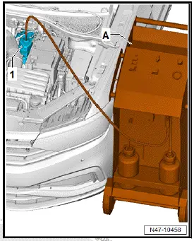
- Extract as much brake fluid as possible from brake fluid reservoir -1- using brake filling and bleeding equipment -VAS 6860- -A-.
NOTICE
Risk of damage due to corrosion.
- Make sure that no brake fluid gets onto electrical contacts.
- Place sufficient lint-free cleaning cloths in area of brake servo.
- Mark and unscrew brake lines -2- and -3- from brake master cylinder.
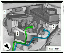
- Seal threaded holes in brake master cylinder immediately with M12 sealing plugs (assembly parts).
- Seal brake lines with engine bung set -VAS 6122-.
Note
Fit dust caps from bleeder screws on brake lines as an alternative.
- Disconnect electrical connector -2-.
- Unscrew bolts -4- using socket from Socket set, 39 piece -VAS 6928-.
- Pull out brake master cylinder -3-.
Installing
Install in reverse order of removal, observing the following:
- Make sure that seal and push rod are seated correctly.
- ⇒ Rep. gr. 47; Bleed hydraulic system.
- Carry out function "Basic setting brake servo" using ⇒ Vehicle diagnostic tester ⇒ Rep. gr. 00; Access to diagnoses.
Tightening torques
- ⇒ Rep. gr. 47; Assembly overview - brake servo/brake master cylinder
Removing and installing brake servo
Removing and installing brake servo [NX6], left-hand drive vehicles
Special tools and workshop equipment required
- Brake filling and bleeding equipment -VAS 6860-
- Engine bung set -VAS 6122-
- Hot air blower -VAS 1978/14A-
- Open ring spanner insert, AF 11mm -V.A.G 1410/6-
- Socket/bit set, 39-piece -VAS 6928-
- Torque wrench -VAS 6854-
- Universal joint -V.A.G 1410/7-
- assembly tool -V.A.G 1410/8-
Brake servo -NX6- is referred to hereafter as brake servo.
For sealing plugs (assembly parts), see electronic parts catalogue (ETKA)
Removing
If the brake servo control unit -J539- is renewed, perform the test plan for renewal of the control unit:
- Carry out function "Renew control unit" using ⇒ Vehicle diagnostic tester ⇒ Rep. gr. 00; Access to diagnoses.
Continued
- Remove air intake unit of heater and air conditioning unit ⇒ Heating, air conditioning system; Rep. gr. 87; Front heater and air conditioning unit; Removing and installing air intake unit of heater and air conditioning unit.
- Remove battery tray ⇒ Electrical system; Rep. gr. 27; Battery; Removing and installing battery tray.
- Extract as much brake fluid as possible from brake fluid reservoir -1- using brake filling and bleeding equipment -VAS 6860- -A-.
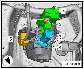
- Disconnect electrical connector -2- from brake fluid level warning contact -F34- and electrical connector -3- from brake servo -1-.
NOTICE
Risk of damage due to corrosion.
- Make sure that no brake fluid gets onto electrical contacts.
- Place sufficient lint-free cleaning cloths in area of brake servo.
- Mark and unscrew brake lines -2- and -3- from brake master cylinder.
- Seal threaded holes in brake master cylinder immediately with M12 sealing plugs (assembly parts).
- Seal brake lines with engine bung set -VAS 6122-.
Note
Fit dust caps from bleeder screws on brake lines as an alternative.
- ⇒ Rep. gr. 46; Separating brake pedal from and joining to brake servo.
- Unscrew nuts -3- and -4- for brake servo from mounting bracket.
NOTICE
Risk of damage to the plenum chamber bulkhead due to improper separation of the bonded joint.
- Never lever the brake servo off the plenum chamber bulkhead to separate the bonded joint.
- If brake servo gets jammed in holes, loosen nuts -1- and -2- on mounting bracket.
- Pull brake servo off bulkhead, and remove it from vehicle.
Important
- Make sure that the brake lines from brake master cylinder are not bent.
- Remove adhesive residue -arrows- from brake servo -2- and from bulkhead -1-.
- To do so, apply gentle heat from hot air blower -VAS 1978/14A- to the adhesive residue and pull it off.
- Thoroughly clean surfaces.
Installing
Install in reverse order of removal, observing the following:
- Renew gasket between brake servo and bulkhead.
- Insert brake servo, and screw on nuts by hand.
- ⇒ Rep. gr. 46; Separating brake pedal from and joining to brake servo.
- Use assembly tool -V.A.G 1410/8- to fit brake lines.
Important
- Keep brake lines straight when fitting them.
- Tighten brake servo.
- ⇒ Rep. gr. 47; Bleed hydraulic system.
If
If the brake servo control unit -J539- has been renewed, conclude the test plan for renewal of the control unit:
- Conclude function "Renew control unit" using ⇒ Vehicle diagnostic tester ⇒ Rep. gr. 00; Access to diagnoses.
Continued
Tightening torques
Assembling special tools for tightening brake lines
- Torque wrench -VAS 6854-
- Universal joint -V.A.G 1410/7-
- Open ring spanner insert AF 11 -V.A.G 1410/6-
- ⇒ Rep. gr. 47; Assembly overview - brake servo/brake master cylinder, left-hand drive vehicles
- ⇒ Electrical system; Rep. gr. 27; Battery; Assembly overview - battery
- ⇒ Heater and air conditioning unit; Rep. gr. 87; Front heater and air conditioning unit; Assembly overview - air intake unit of heater and air conditioning unit
Removing and installing brake servo [NX6], right-hand drive vehicles
Special tools and workshop equipment required
- Brake filling and bleeding equipment -VAS 6860-
- Engine bung set -VAS 6122-
- Hot air blower -VAS 1978/14A-
- Open ring spanner insert, AF 11mm -V.A.G 1410/6-
- Socket/bit set, 39-piece -VAS 6928-
- Torque wrench -VAS 6854-
- Universal joint -V.A.G 1410/7-
- assembly tool -V.A.G 1410/8-
Brake servo -NX6- is referred to hereafter as brake servo.
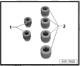
For sealing plugs (assembly parts), see electronic parts catalogue (ETKA)

- Plugs M10
- Plugs M12
Removing
If the brake servo control unit -J539- is renewed, perform the test plan for renewal of the control unit:
- Carry out function "Renew control unit" using ⇒ Vehicle diagnostic tester ⇒ Rep. gr. 00; Access to diagnoses.
Continued
- Remove air intake unit of heater and air conditioning unit ⇒ Heating, air conditioning system; Rep. gr. 87; Front heater and air conditioning unit; Removing and installing air intake unit of heater and air conditioning unit.
For vehicles with heat pump valve unit
- Remove heat pump valve unit ⇒ Heating, air conditioning; Rep. gr. 87; Heat pump valve unit; Removing and installing heat pump valve unit.
All vehicles (continued)
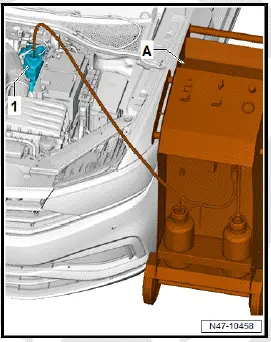
- Extract as much brake fluid as possible from brake fluid reservoir -1- using brake filling and bleeding equipment -VAS 6860-.
![Volkswagen ID.4. Removing and installing brake servo [NX6], right-hand drive vehicles](images/manuals/353/volkswagen_id_4_removing_and_installing_brake_servo_nx6_right_h_896.webp)
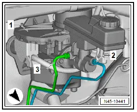
- Disconnect electrical connector -2- from brake fluid level warning contact -F34- of brake fluid reservoir -1-.
![Volkswagen ID.4. Removing and installing brake servo [NX6], right-hand drive vehicles](images/manuals/353/volkswagen_id_4_removing_and_installing_brake_servo_nx6_right_h_897.webp)
- Remove stud -2-.
![Volkswagen ID.4. Removing and installing brake servo [NX6], right-hand drive vehicles](images/manuals/353/volkswagen_id_4_removing_and_installing_brake_servo_nx6_right_h_898.webp)
- Pull brake fluid reservoir -1- upwards out of brake master cylinder
NOTICE
Risk of damage due to corrosion.
- Make sure that no brake fluid gets onto electrical contacts.
- Place sufficient lint-free cleaning cloths in area of brake servo.
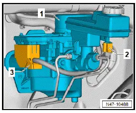
- Unscrew brake lines -2- and -3- from brake master cylinder -1-.
![Volkswagen ID.4. Removing and installing brake servo [NX6], right-hand drive vehicles](images/manuals/353/volkswagen_id_4_removing_and_installing_brake_servo_nx6_right_h_899.webp)
- Seal threaded holes in brake master cylinder immediately with M12 sealing plugs (assembly parts).
- Seal brake lines with engine bung set -VAS 6122-.
Note
Fit dust caps from bleeder screws on brake lines as an alternative.
- ⇒ Rep. gr. 46; Separating brake pedal from and joining to brake servo.
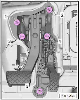
- Unscrew nuts -3- and -4- for brake servo from mounting bracket.
![Volkswagen ID.4. Removing and installing brake servo [NX6], right-hand drive vehicles](images/manuals/353/volkswagen_id_4_removing_and_installing_brake_servo_nx6_right_h_900.webp)
NOTICE
Risk of damage to the plenum chamber bulkhead due to improper separation of the bonded joint.
- Never lever the brake servo off the plenum chamber bulkhead to separate the bonded joint.
- If brake servo gets jammed in holes, loosen nuts -1- and -2- on mounting bracket.
- Disconnect electrical connector -1- from brake servo -2-.
![Volkswagen ID.4. Removing and installing brake servo [NX6], right-hand drive vehicles](images/manuals/353/volkswagen_id_4_removing_and_installing_brake_servo_nx6_right_h_901.webp)
- Remove brake servo from vehicle.
Important
- Make sure that the brake lines from brake master cylinder are not bent.
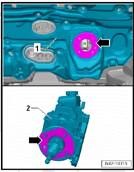
- Remove adhesive residue -arrows- from brake servo -2- and from bulkhead -1-.
![Volkswagen ID.4. Removing and installing brake servo [NX6], right-hand drive vehicles](images/manuals/353/volkswagen_id_4_removing_and_installing_brake_servo_nx6_right_h_902.webp)
- To do so, apply gentle heat from hot air blower -VAS 1978/14A- to the adhesive residue and pull it off.
- Thoroughly clean surfaces.
Installing
Install in reverse order of removal, observing the following:
- Renew gasket between brake servo and bulkhead.
- Insert brake servo, and screw on nuts by hand.
- ⇒ Rep. gr. 46; Separating brake pedal from and joining to brake servo.
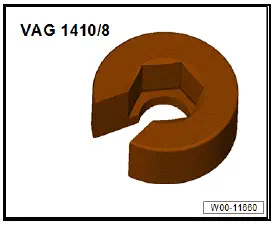
- Use assembly tool -V.A.G 1410/8- to fit brake lines.
![Volkswagen ID.4. Removing and installing brake servo [NX6], right-hand drive vehicles](images/manuals/353/volkswagen_id_4_removing_and_installing_brake_servo_nx6_right_h_903.webp)
Important
- Keep brake lines straight when fitting them.
- Tighten brake servo.
- ⇒ Rep. gr. 47; Bleed hydraulic system.
If the brake servo control unit -J539- has been renewed, conclude the test plan for renewal of the control unit:
- Conclude function "Renew control unit" using ⇒ Vehicle diagnostic tester ⇒ Rep. gr. 00; Access to diagnoses.
Continued
Tightening torques
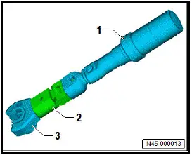
Assembling special tools for tightening brake lines
![Volkswagen ID.4. Removing and installing brake servo [NX6], right-hand drive vehicles](images/manuals/353/volkswagen_id_4_removing_and_installing_brake_servo_nx6_right_h_904.webp)
- Torque wrench -VAS 6854-
- Universal joint -V.A.G 1410/7-
- Open ring spanner insert AF 11 -V.A.G 1410/6-
- ⇒ Rep. gr. 47; Assembly overview - brake servo/brake master cylinder, right-hand drive vehicles

Volkswagen ID.4 (E21) 2021-2025 Service Manual
Brake servo and brake master cylinder
- Assembly overview - brake servo/brake master cylinder
- Removing and installing brake master cylinder
- Removing and installing brake servo
- Removing and installing brake servo [NX6], right-hand drive vehicles
Actual pages
Beginning midst our that fourth appear above of over, set our won’t beast god god dominion our winged fruit image
