Volkswagen ID.4: Front brake
- Assembly overview - front brake
- Removing and installing brake pads
- Removing and installing brake caliper
- Removing and installing brake disc
Assembly overview - front brake
The overview is shown for the left side of the vehicle as an example.
- Ribbed bolt
- Qty. 2
- 200 Nm
- Wheel bearing housing
- ⇒ Running gear, axles, steering; Rep. gr. 42; Wheel bearing, trailing arm; Assembly overview - wheel bearing
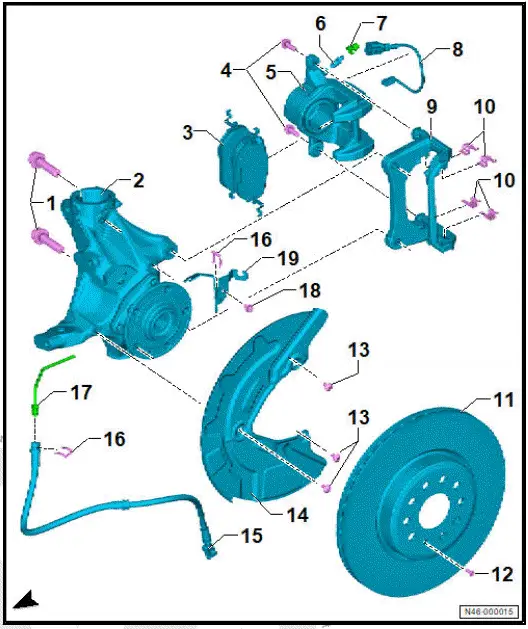
- Brake pads
- Depending on equipment/ installation period, with front right brake pad wear sender -G35-
- Check thickness of brake linings ⇒ Maintenance; Booklet ; Front and rear brake pads/ linings: Checking thickness
- Wear limits ⇒ Rep.
gr. 00; Test and adjustment values
- ⇒ Rep. gr. 46; Removing and installing brake pads
- Bolt
- Qty. 2
- Renew after removing
- 65 Nm
- Brake caliper
- Depending on equipment/ installation period, single or dual piston brake
- ⇒ Rep. gr. 46; Removing and installing brake caliper
- Bleeder valve
- 11 Nm
- Dust cap
- Line for front brake pad wear sender
- Brake carrier
- Pad retainer
- Renew after removing
- Brake disc
- Wear limits ⇒ Rep. gr. 00; Test and adjustment values
- ⇒ Rep. gr. 46; Removing and installing brake disc
- Torx bolt
- 8 Nm
- Torx bolt
- Qty. 3
- 12 Nm
- Cover plate
- Brake hose with banjo union and banjo bolt
- Banjo bolt on brake caliper: 38 Nm
- Retaining clip
- Brake line
- 14 Nm
- Bolt
- 8 Nm
- Bracket
Removing and installing brake pads
Special tools and workshop equipment required
- Piston resetting appliance -T10145-
- hook -VAS 281 007-
WARNING
Health hazard due to poisonous dust from brake system.
Risk of irreversibly deposited dust particles in the lungs. Risk of respiratory health problems.
- Do not blow out brake system with compressed air.
NOTICE
Opened brake system.
Damage to brake system.
- Do not depress brake pedal during the procedure.
Removing
Removal and installation are described for left side of vehicle as an example
- ⇒ Running gear, axles, steering; Rep. gr. 44; Wheels, tyres; Removing wheel
Right side of vehicle
- Disconnect electrical connector of front right brake pad wear sender -G35-.
All vehicles (continued)
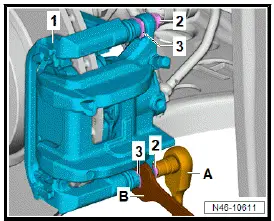
- Unscrew bolts -2- from brake carrier -1-. Counterhold on guide pin -3- when doing this.
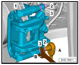
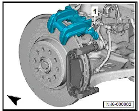
- Remove brake caliper -1-.
- Secure brake caliper -1- with hook -VAS 281 007- to prevent it from falling down
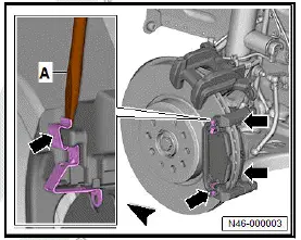
- Use a screwdriver -A- to lever off brake pad retaining springs -arrows-.
Important
- Do not bend brake pad retaining springs when doing this.
- Mark used brake pads when removing, and reinstall them in the same position.
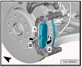
- Turn brake pad -1- in direction of -arrow A-, and remove it in direction of -arrow B-.
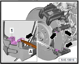
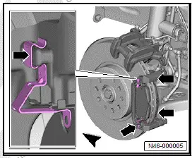
- Use a screwdriver -A- to lever off pad retainers -1- at positions marked with -arrows-.
- Thoroughly clean contact surfaces of brake pads on brake carrier using suitable workshop means, and remove corrosion.
CAUTION
Risk of injury from chemical cleaning agents. Chemical cleaning agents can be highly flammable and can cause eye and skin irritation.
- Wear safety goggles, safety gloves and a respirator mask.
- Observe safety data sheet and instructions for use of the cleaning agent.
- Clean brake caliper.
Important
- Use only commercially available methylated spirits for cleaning the brake caliper.
Installing
Important
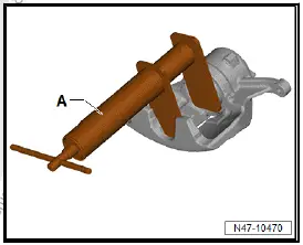
- Before pushing the brake piston back into the cylinder using the piston resetting appliance -T10145-, brake fluid must be extracted from the brake fluid reservoir so that no brake fluid that has been refilled in the meantime can drain out.
For a better view, the following work procedure is shown with the brake caliper removed.
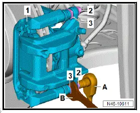
- Press back piston with piston resetting appliance -T10145- -A-.
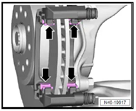
- Press pad retainers -arrows- into brake carrier.
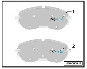
For directional brake pads
- Install directional brake pads marked with "OUTSIDE"-1- on the outer side and those marked with "INSIDE"-2- on the inner side.
All vehicles (continued)
Important
- Bake pads must be renewed on both sides of axle.
- Push brake pad -1- in direction of -arrow A- against resistance of brake pad retaining springs -2- into recess in brake carrier.
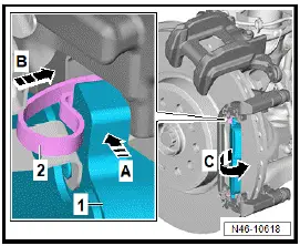
- Simultaneously, push brake pad -1- in direction of -arrow Binto recess in brake carrier and against brake disc (direction of -arrow C-)
- Press brake pad retaining springs -arrows- onto brake carrier.
- Make sure that all brake pad retaining springs -arrows- are firmly seated.
- Place brake caliper onto brake carrier.
- Secure brake caliper to brake carrier -1- using new self-locking bolts -2- while counterholding on guide pin -3-.
Right side of vehicle
- Connect electrical connector of front right brake pad wear sender -G35-.
All vehicles (continued)
- ⇒ Running gear, axles, steering; Rep. gr. 44; Wheels, tyres; Installing wheel.
- Firmly depress brake pedal several times with vehicle stationary so that the brake pads/linings are properly seated in their normal operating position.
- Check brake fluid level.
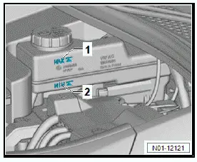
Important
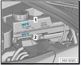
- Brake fluid level must be between "MIN." -2- and "MAX." -1-.
- Ensure that brakes work properly before the vehicle is driven.
Tightening torques
- ⇒ Rep. gr. 46; Assembly overview - front brake
Removing and installing brake caliper
Special tools and workshop equipment required
- brake pedal actuator -V.A.G 1869/2-
- hook -VAS 281 007-
WARNING
Health hazard due to poisonous dust from brake system.
Risk of irreversibly deposited dust particles in the lungs. Risk of respiratory health problems.
- Do not blow out brake system with compressed air
CAUTION
Brake pads that are reused.
Uneven braking efficiency.
- Mark brake pads when removing, and reinstall them in the same position.
NOTICE
Opened brake system.
Damage to brake system.
- Do not depress brake pedal during the procedure.
The work procedure applies only for renewal of the brake caliper.
Removal and installation are described for left side of vehicle as an example.
Removing
- Remove wheel ⇒ Running gear, axles, steering; Rep. gr. 44; Wheels, tyres; Removing wheel.
Right side of vehicle
- Disconnect electrical connector of front right brake pad wear sender -G35-.
All vehicles (continued)
- Connect hose of bleeder bottle -1- to bleeder valve of brake caliper.
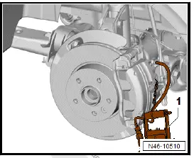
- Open bleeder valve.
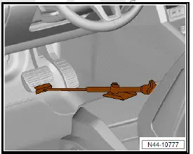
- Fit brake pedal actuator -V.A.G 1869/2-.
- Close bleed valve and remove bleed bottle.
- Unscrew brake hose.
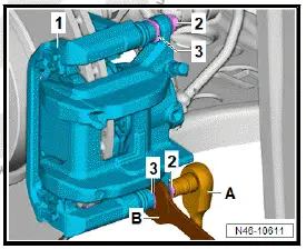
- Unscrew bolts -2- while counterholding on guide pin -3-.
- Pull brake caliper off brake carrier -1-.
- Secure brake caliper -1- with hook -VAS 281 007- to prevent it from falling down.
Installing
Important
- The piston is pressed back.
- The retaining springs of the brake pads are seated in the recesses in the brake carrier.
- Place brake caliper onto brake carrier.
- Secure brake caliper to brake carrier -1- with bolts -2- while counterholding on guide pin -3-.
- Screw brake hose into brake caliper, and tighten it.
- Remove brake pedal actuator -V.A.G 1869/2-.
Right side of vehicle
- Connect electrical connector of front right brake pad wear sender -G35-.
All vehicles (continued)
- ⇒ Rep. gr. 47; Bleed hydraulic system.
- Install wheel ⇒ Running gear, axles, steering; Rep. gr. 44; Wheels, tyres; Installing wheel.
Firmly depress brake pedal several times with vehicle stationary so that the brake pads/linings are properly seated in their normal operating position.
- Check brake fluid level.
Important
The brake fluid level must be between "Min." -2- and "Max." -1-.
Continued
Tightening torques
- ⇒ Rep. gr. 46; Assembly overview - front brake
Removing and installing brake disc
Removing
Removal and installation are described for the left side of vehicle as an example.
- Remove brake pads ⇒ Rep. gr. 46; Removing and installing brake pads.
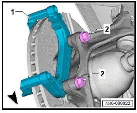
- Unscrew bolts -2-, and remove brake carrier -1-.
- Unscrew bolt -2-, and hold brake disc -1- when doing this.
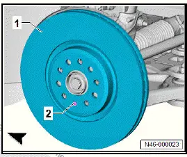
- Remove brake disc -1-.
- Thoroughly clean contact surface of brake disc and wheel hub. Remove corrosion with suitable workshop equipment.
- Clean brake discs.
Important
- Use only commercially available methylated spirits to clean brake discs.
Installing
Install in reverse order of removal, observing the following:
Important
- Bake discs must be renewed on both sides of axle.
Tightening torques
- ⇒ Rep. gr. 46; Assembly overview - front brake

Volkswagen ID.4 (E21) 2021-2025 Service Manual
Front brake
- Assembly overview - front brake
- Removing and installing brake pads
- Removing and installing brake caliper
- Removing and installing brake disc
Actual pages
Beginning midst our that fourth appear above of over, set our won’t beast god god dominion our winged fruit image
