Volkswagen ID.4: Rear brake
- Assembly overview - rear brake, drum brake version
- Assembly overview - brake shoes
- Removing and installing brake backplate
- Removing and installing gasket for brake backplate
- Removing and installing brake drum
- Removing and installing brake shoes
Assembly overview - rear brake, drum brake version
The overview is shown for the left side of the vehicle as an example.
- Multi-point socket head bolt
Qty. 4 ❑ N.108.626.01 ❑ Renew after removing ❑ M10 x 58 ❑ 50 Nm +180º
- Bracket
- Wheel bearing housing
- ⇒ Running gear, axles, steering; Rep. gr. 42; Wheel bearing, trailing arm; Assembly overview - wheel bearing
- Gasket
- ⇒ Rep. gr. 46; Removing and installing gasket for brake backplate
- Brake backplate with brake shoes
- ⇒ Rep. gr. 46; Removing and installing brake backplate
- Multi-point socket head bolt
- Qty. 3
- M8 x 25
- 20 Nm +45º
- Plug
- Brake drum
- Wear limit ⇒ Rep.
gr. 00; Test and adjustment values
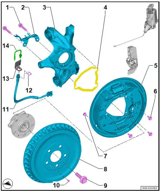
- Bolt
- ⇒ Running gear, axles, steering; Rep. gr. 42; Wheel bearing, trailing arm; Assembly overview - wheel bearing
- Torx bolt
- M6 x 16
- 8 Nm
- Brake hose with banjo union and banjo bolt
- Ensure correct installation position
- Banjo bolt on wheel brake cylinder: 45 Nm
- Clip
- Retainer
- Brake line
- 14 Nm
Assembly overview - brake shoes
The overview is shown for the left side of the vehicle as an example.
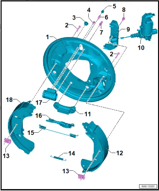
- Brake carrier
- Hold-down pin
- Sealing plug
- Bolt
- 10 Nm
- Protective cap for bleeder screw
- Bleeder valve
- 10 Nm
- Pin
- For brake hose adjustment
- Bolt
- 8 Nm
- Bracket for parking brake motor
- Left parking brake motor -V282-/right parking brake motor -V283-
- ⇒ Rep. gr. 46; Removing and installing parking brake motor [V282]/ [V283]
- Lower support
- Brake shoe
- Check thickness of brake linings ⇒ Maintenance; Booklet ; Front and rear brake pads/ linings: Checking thickness
- Renew on both sides
- Wear limit ⇒ Rep. gr. 00; Test and adjustment values
- ⇒ Rep. gr. 46; Removing and installing brake shoes
- Retaining clip
- For locking brake shoe ❑ Qty. 2
- Lower return spring
- Upper return spring
- Automatic adjuster
- Left-side version with annular groove on coarse adjuster
- With adjustment screw
- Wheel brake cylinder
- ⇒ Rep. gr. 47; Check wheel brake cylinder for leaks
- Brake shoe with lever for parking brake
- Check thickness of brake linings ⇒ Maintenance; Booklet ; Front and rear brake pads/linings: Checking thickness
- Renew on both sides
- Wear limit ⇒ Rep. gr. 00; Brake technical data
- ⇒ Rep. gr. 46; Removing and installing brake shoes
Removing and installing brake backplate
Special tools and workshop equipment required
- hook -VAS 281 007-
Removal and installation are described for left side of vehicle as an example.
Removing
- Remove wheel bearing unit ⇒ Running gear, axles, steering; Rep. gr. 42; Wheel bearing, trailing arm; Removing and installing wheel bearing unit .
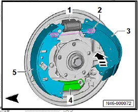
- Unscrew bolt -5-.
- Unscrew bolts -2-.
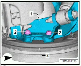
- Unscrew bolts -arrows-.
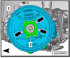
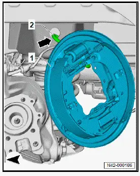
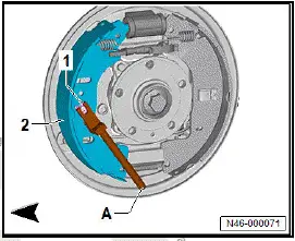
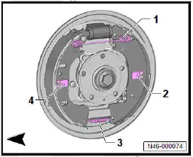
- Detach brake backplate -1- from wheel bearing housing -2-.
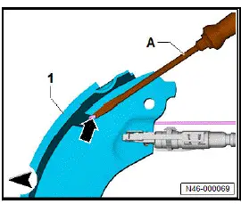
- Secure brake backplate -1- to body -arrow- using hook -VAS 281 007- -2-.
Installing
Install in reverse order of removal, observing the following:
- Renew gasket for brake backplate ⇒ Running gear, axles, steering; Rep. gr. 42; Wheel bearing, trailing arm; Removing and installing gasket for brake backplate.
Tightening torques
- ⇒ Brake system; Rep. gr. 46; Rear brake; Assembly overview - rear brake, drum brake
- ⇒ Brake system; Rep. gr. 46; Rear brake; Assembly overview - brake shoes
Removing and installing gasket for brake backplate
Special tools and workshop equipment required
- Adhesive strip remover -VAS 6349-
- guide bolt -T10406-
- template -T10656-
Removal and installation are described for left side of vehicle as an example.
Removing
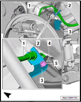
- Remove brake backplate ⇒ Brake system; Rep. gr. 46; Rear brake; Removing and installing brake backplate.
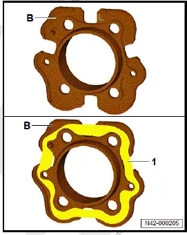
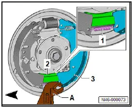
- Remove sealant residue -2- using adhesive strip remover -VAS 6349-.

- Clean sealing surfaces using commercially available methylated spirits.
Important
- Cleaned surfaces must be free of greasing and sealing agents.
- Remove sealant residue -2- using adhesive strip remover.

- Clean sealing surfaces using commercially available methylated spirits.
Important
- Cleaned surfaces must be free of greasing and sealing agents.
Installing
Install in reverse order of removal, observing the following:
- Screw guide pin -T10406- -A- into holes of wheel bearing housing -1-.

Important
- If gaskets -1- were not fitted at factory, retrofitting must always be carried separately for each axle.
- Insert gasket -1- into side "L" of template -T10656- -B-
Important
- Note markings on template -B- for relevant side of vehicle.
- Pull off protective film.
- Fit template -B- over guide pins -A- onto wheel bearing housing -1-.

- Press on gasket in marked areas -arrows-.
- Remove template -B-.
- Press on gasket -2- over entire circumference.

- Pull off protective film -2-.
Removing and installing brake drum
WARNING
Health hazard due to poisonous dust from brake system.
Risk of irreversibly deposited dust particles in the lungs. Risk of respiratory health problems.
- Do not blow out brake system with compressed air.
Removal and installation are described for the left side of vehicle as an example.
Important
- Do not operate the brake when the system is open.
Removing
- ⇒ Running gear, axles, steering; Rep. gr. 44; Wheels, tyres; Removing wheel.
- Carry out function "Brake service, rear" using ⇒ Vehicle diagnostic tester ⇒ Rep. gr. 00; Access to diagnoses.
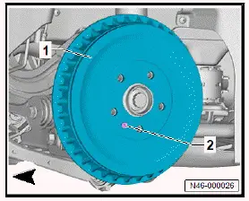
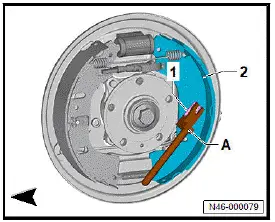
- Unscrew bolt -2-, and remove brake drum -1-.
Installing
Install in reverse order of removal, observing the following:
- Carry out function "Brake service, rear" using ⇒ Vehicle diagnostic tester ⇒ Rep. gr. 00; Access to diagnoses.
Tightening torques
- ⇒ Rep. gr. 46; Assembly overview - rear brake, drum brake version
Removing and installing brake shoes
Special tools and workshop equipment required
- Assembly tool -T30114-
- assembly device -T10635-
- assembly pliers -T10623-
WARNING
Health hazard due to poisonous dust from brake system.
Risk of irreversibly deposited dust particles in the lungs. Risk of respiratory health problems.
- Do not blow out brake system with compressed air.
Removal and installation are described for the left side of vehicle as an example.
Important
- Do not operate brake when system is open.
Removing
- Remove brake drum ⇒ Rep. gr. 46; Removing and installing brake drum.
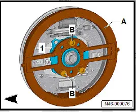
- Turn clip -1-.

- Use assembly tool -T30114- -A- to release and pull out clip -1- in direction of -arrow B-. Press against pin from behind while doing so.
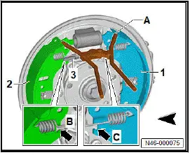
- Using commercially available water pump pliers -A-, lever brake shoe -1- in direction of -arrow B- out of reaction block -3-.
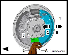
- Put brake shoe -1- in direction of -arrow C- before reaction block -3-.
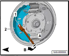
- Unhook lower return spring -2-.
- Bring clip -1- in position.
- Use assembly tool -T30114- -A- to release and pull out clip -1- in direction of -arrow B-. Press against pin from behind while doing so.
NOTICE
Risk of damage to wheel brake cylinder, boot and automatic adjuster through improper handling.
Any damage will have a negative effect on the function of the automatic adjuster and the brake.
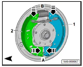
- Remove both brake shoes.
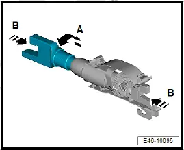
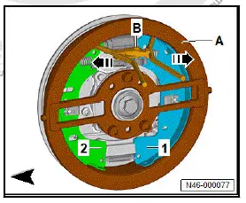
- Press together brake shoes -1- and -2- in direction of -arrows A-, and pull in direction of -arrows B-.
- Detach handbrake cable -2- from handbrake lever -1-.
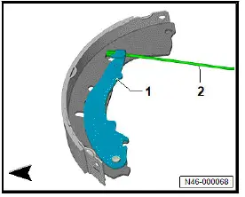
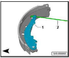
- Lever upper return spring -arrow- out of brake shoe -1- using commercially available screwdriver -A-.
Installing
Install in reverse order of removal, observing the following:
CAUTION
Risk of injury from chemical cleaning agents. Chemical cleaning agents can be highly flammable and can cause eye and skin irritation.
- Wear safety goggles, safety gloves and a respirator mask.
- Observe safety data sheet and instructions for use of the cleaning agent.
- Clean brake system.
Important
- Use only commercially available methylated spirits for cleaning the brake system.
11"- brake system models
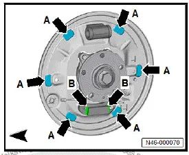
- Grease contact surfaces -arrows A- and -arrows B- with lubricating paste. For allocation, see ⇒ Electronic parts catalogue (ETKA).
All vehicles (continued)
13"- brake system models
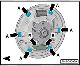
- Grease contact surfaces -arrows A- with lubricating paste.
For allocation, see ⇒ Electronic parts catalogue (ETKA).
All vehicles (continued)
- Attach handbrake cable -2- to handbrake lever -1-.
- Install brake shoe -2- with handbrake lever.
- Use assembly tool -T30114- -A- to insert clip -1-. Press against pin from behind while doing so.
- Insert upper return spring -2- into brake shoes -3- and -5-.
- Position brake shoe -3- on wheel brake cylinder -1-, swing in direction of -arrow-, and place it in front of reaction block -4-.
- Attach lower return spring -1-, and lever brake shoe -3- into reaction block -2- using commercially available water pump pliers -2-.
- Use assembly tool -T30114- -A- to insert clip -1-. Press against pin from behind while doing so.
- Turn clips -2- and -4- to horizontal, and align return springs at top -1- and bottom -3- in position.
- Note that the automatic adjuster has a fine mechanism.
NOTICE
Risk of damage to automatic adjuster from improper handling.
Deformations can negatively influence the function of the automatic adjuster.
- Handle components with care.
- Do not deform components.
- No adjustment on gear wheel.
Important
- To ensure that the brake functions optimally, pre-adjustment of the automatic adjuster is required. The automatic adjuster must be free to rotate and it should be possible to install it without applying force.
- Turn bolt in direction of -arrow A- for "rough adjustment".
- Push regulator in direction of -arrow B- to activate "fine adjustment".
NOTICE
Malfunction and risk of damage to the rear brake due to incorrect adjustment of the automatic adjuster.
- The automatic adjuster must be adjusted manually to attain the requisite diameter at the brake shoes.
- Screw automatic adjuster in or out, in such a way that it sits between both brake shoes with slight pretension thus adjusting the rear brake.
- Press brake shoes -1- and -2- apart using assembly pliers -T10623- -A-.
- Position automatic adjuster in recesses -arrow B- and -arrow C-.
- Note installation position of automatic adjuster -1-.
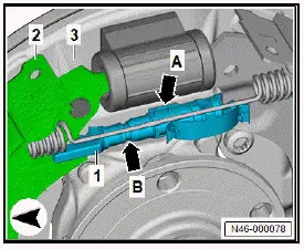
- Thermo clip -arrow A- must point towards brake backplate -3- while threaded side -arrow B- points towards brake shoe -2- with handbrake lever.
- Shorter guide of threaded side -arrow B- must point towards brake backplate -3-.
- Fit assembly device -T10635- -A- to wheel hub -1- using enclosed bolts -B-.
Important
- Bolts -B- of assembly device -T10635- -A- must be screwed into through-holes.
- Using assembly pliers -T10623- -B-, repeatedly push brake shoes -1- and -2- in direction of -arrows- until no adjustment is visible nor audible on automatic adjuster.
- Remove setting tool -T10635- -A-.
- Install brake drum ⇒ Rep. gr. 46; Removing and installing brake drum.
If the brake shoes have been renewed:
- Check the brake fluid level ⇒ Maintenance; Booklet .
All vehicles (continued)
- Check function of brake.
- Carry out road test.
Tightening torques
- ⇒ Rep. gr. 46; Assembly overview - rear brake, drum brake version

Volkswagen ID.4 (E21) 2021-2025 Service Manual
Rear brake
- Assembly overview - rear brake, drum brake version
- Assembly overview - brake shoes
- Removing and installing brake backplate
- Removing and installing gasket for brake backplate
- Removing and installing brake drum
- Removing and installing brake shoes
Actual pages
Beginning midst our that fourth appear above of over, set our won’t beast god god dominion our winged fruit image
