Volkswagen ID.4: Rear seats
- Assembly overview - bench seat/individual seats
- Assembly overview - rear seat backrest
- Assembly overview - centre armrest
- Removing and installing bench seat/individual seats
- Removing and installing seat pan
- Removing and installing head restraint guide
- Removing and installing rear seat backrest
- Removing and installing back panel trim
- Removing and installing trim for locking mechanism
- Removing and installing trim frame for load-through hatch
- Removing and installing flap for load-through hatch
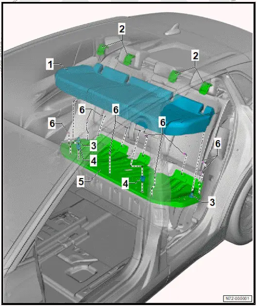
Assembly overview - bench seat/individual seats
- Bench seat
- Depending on equipment/ version
- ⇒ Rep. gr. 72 ; Removing and installing bench seat/individual seats
- Child seat anchor guide in bench seat
- Qty. 4
- ⇒ Rep. gr. 74 ; Removing and installing cover and padding of rear bench seat
- Arrester
- Qty. 2
- Grommet
- Qty. 2
- Renew after removing
- Seat pan
- ⇒ Rep. gr. 72 ; Removing and installing seat pan
- Bolt
- Qty. 10
- 8 Nm
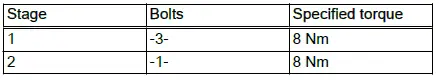
Specified torque and tightening sequence
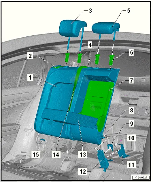
Assembly overview - rear seat backrest
The overview is shown for the rear seat backrest (2/3) as an example.
- Rear seat backrest
- ⇒ Rep. gr. 72 ; Removing and installing rear seat backrest
- Locking mechanism for rear seat backrest
- ⇒ Rep. gr. 72 ; Assembly overview - locking mechanism
- ⇒ Rep. gr. 72 ; Removing and installing locking mechanism for rear seat backrest
- Outer head restraint
- ⇒ Rep. gr. 72 ; Removing and installing head restraint
- Rear belt guide
- Depending on equipment/ version
- ⇒ Rep. gr. 69 ; Removing and installing rear belt guide
- Centre head restraint
- ⇒ Rep. gr. 72 ; Removing and installing head restraint
- Head restraint guide
- ⇒ Rep. gr. 72 ; Removing and installing head restraint guide
- Flap for load-through hatch
- Depending on equipment/ version
- ⇒ Rep. gr. 72 ; Removing and installing flap for load-through hatch
- Inner pivot pin
- 13.5 Nm
- Locking bar
- ⇒ Rep. gr. 72 ; Removing and installing rear seat backrest
- Bolt
- 9 Nm
- Cover
- ⇒ Rep. gr. 72 ; Removing and installing rear seat backrest
- Centre mount
- Centre armrest
- Depending on equipment/version
- ⇒ Rep. gr. 72 ; Assembly overview - centre armrest
- ⇒ Rep. gr. 72 ; Removing and installing centre armrest
- Rear centre three-point seat belt
- Depending on equipment/version
- ⇒ Rep. gr. 69 ; Removing and installing rear three-point seat belt
- Outer support pin
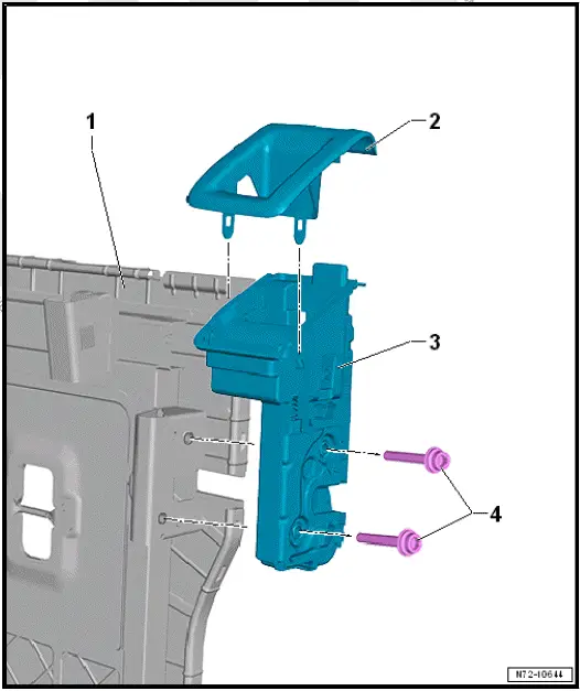
Assembly overview - locking mechanism
The overview is shown for the left side of vehicle as an example.
- Frame, rear seat backrest
- Locking mechanism trim
- ⇒ Rep. gr. 72 ; Removing and installing locking mechanism trim
- Locking mechanism for rear seat backrest
- ⇒ Rep. gr. 72 ; Removing and installing locking mechanism for rear seat backrest
- Bolt
- qty. 2
- 23 Nm
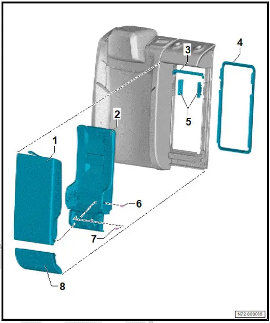
Assembly overview - centre armrest
- Centre armrest
- ⇒ Rep. gr. 72 ; Removing and installing centre armrest
- Flap for load-through hatch
- ⇒ Rep. gr. 72 ; Removing and installing flap for load-through hatch
- Stop strip
- ⇒ Rep. gr. 72 ; Removing and installing trim frame for loadthrough hatch
- Trim frame for loadthrough hatch
- ⇒ Rep. gr. 72 ; Removing and installing trim frame for loadthrough hatch
- Flap catch trim
- Qty. 2
- ⇒ Rep. gr. 72 ; Removing and installing trim frame for loadthrough hatch
- Bolt
- Self-tapping
- Qty. 2
- Renew after removing
- 12 Nm
- Bolt
- Qty. 2
- 8 Nm
- Intermediate padding
- ⇒ Rep. gr. 74 ; Removing and installing intermediate padding, backrest with load-through hatch
Removing and installing bench seat/individual seats
Special tools and workshop equipment required
- removal tool - T40445-
Removing
- Move front seats to foremost position.
- Remove child seat anchor guides ⇒ Rep. gr. 74 ; Removing and installing cover and padding of rear bench seat .
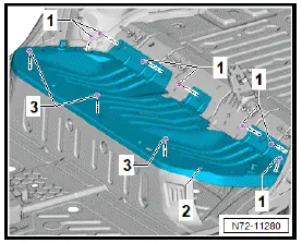
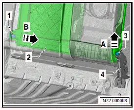
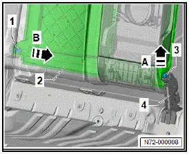
- Push in removal tool - T40445- to stop in area of wire hook -2- between bench seat -1- and bracket.
- Push removal tool - T40445- upwards and carefully lever bench seat -1- in direction of -arrow A- out of grommet -3-.
- Repeat procedure on other side -arrow B-.
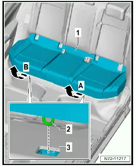
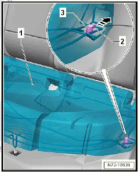
- Slightly raise bench seat -1- at front, and push wire frame -2- in direction of -arrow- out of arresters -3-.
- Disconnect electrical connector.
- Remove bench seat -1-.
Installing
Install in reverse order of removal, observing the following:
- Check body aperture -arrow- for deformation.
Note
Slight remaining deformations are permissible.
- Repair any sheet metal deformations using a plastic hammer.
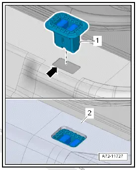
- Raise floor covering -2-, and press new grommets -1- into body apertures -arrow- until they engage audibly.
- Arrange floor covering -2- around grommet taking care not to cover the grommet.
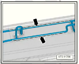
- Before installing the bench seat, check if the wire frame is aligned properly in the area indicated by -arrows-.
- If applicable, bend back deformed wire frame until it is properly aligned again.
Note
Make sure that the wire hooks engage properly.
- Insert bench seat, and firmly press wire hooks into grommets.
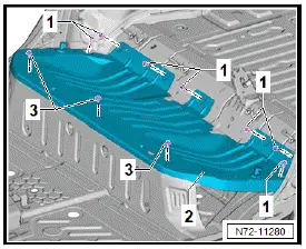
Removing and installing seat pan
Removing
- Remove bench seat ⇒ Rep. gr. 72 ; Removing and installing bench seat/individual seats .
- Fold floor covering in area of seat pan towards front
- Unscrew bolts -1- and -3-
- Remove seat pan -2-.
Installing
Install in reverse order of removal, observing the following:
Tightening torques
- ⇒ Rep. gr. 72 ; Assembly overview - bench seat/individual seats
Removing and installing head restraint
Removing
- Release rear seat backrest, and fold it forwards slightly.
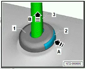
- Press height adjustment release button -2- on head restraint guide -1- in direction of -arrow A-, and hold it there.
- Move head restraint -3- as far as stop upwards -arrow B-.
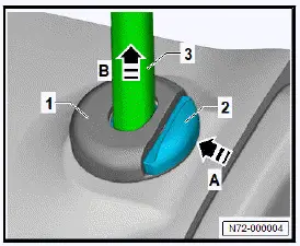
- Press release button -2- on head restraint guide -1- in direction of -arrow A-, and hold it there.
- Pull head restraint -3- in direction of -arrow B- out of head restraint guide -1-, and remove it.
Installing
Install in reverse order of removal.
Removing and installing head restraint guide
Removing
Note
3 commercially available screwdrivers with a blade height of 0.4 mm and a blade width of 8 mm are required for removal.
- Remove head restraint ⇒ Rep. gr. 72 ; Removing and installing head restraint .
- Push cover and padding -1- on outer side slightly downwards.
Note
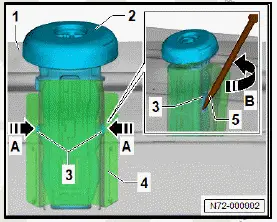
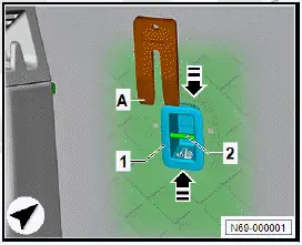
Position 2 screwdrivers next to locking devices so that flat side of screwdriver blade rests against locking device.
- Insert a screwdriver on each side of head restraint channel -4-, and push it in as far as locking device -3-.
- Turn both screwdrivers 90º in direction of -arrow B-, and release locking devices -3- in direction of -arrow A-.
- Using an additional screwdriver, lever head restraint guide -2- off head restraint channel -4
Installing
Install in reverse order of removal.
Removing and installing rear seat backrest
Removing
Removal and installation is described for the rear seat backrest (2/3).
- Remove rear shelf.
Rear seat backrest (2/3)
- Remove rear right belt buckle ⇒ Rep. gr. 69 ; Removing and installing rear right belt buckle .
- Fold down flap for load-through hatch.
All vehicles (continued)
Note
For reasons of clarity, the left rear seat backrest (1/3) is not shown in illustration.
- Pull cover -1- off centre mount -2-.
- Unscrew bolt -2-.
- Fold locking bar -1- in direction of -arrow A-, detach it from centre mount -arrow B-, and remove it.
- Lift out rear seat backrest -2- at inner pivot pin -3- in direction of -arrow A-, and pull it out at outer pivot pins -1- in direction of -arrow B-.
- Remove rear seat backrest -2-.
Installing
Install in reverse order of removal, observing the following:
- Push rear seat backrest -2- in opposite direction of -arrow Bonto outer pivot pin -1-.
- Position inner pivot pin -3- in centre mount -4-.
Tightening torques
- ⇒ Rep. gr. 72 ; Assembly overview - rear seat backrest
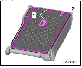
Removing and installing back panel trim
Special tools and workshop equipment required
- Hot air blower - V.A.G 1416-
Removing
- Remove head restraint ⇒ Rep. gr. 72 ; Removing and installing head restraint .
- Fold rear seat backrest towards front.
- Using commercially available plastic wedge -A-, release locking devices in direction of -arrow-, and lever off child seat anchor cover in rear seat backrest -1- upwards.
Note
The back panel trim is bonded to the backrest frame over its entire surface.
- Apply heat from hot air blower - V.A.G 1416- to entire surface of back panel trim -1-, and carefully detach back panel trim from backrest frame -2-.
Installing
Install in reverse order of removal, observing the following:
- Apply adhesive -1- ⇒ Electronic parts catalogue (ETKA) onto outer surface of backrest frame -2-.
- Align back panel trim evenly relative to outer edges of backrest frame -2- and opening for child seat anchor cover in rear seat backrest.
- As soon as desired position has been found, press on back panel trim firmly.
Removing and installing trim for locking mechanism
Removing
- Remove head restraint ⇒ Rep. gr. 72 ; Removing and installing head restraint .
- Using a screwdriver, detach upper and side piping strip for cover in area of locking mechanism trim from rear seat backrest.
Important
- The aid of an additional person is required for the subsequent work steps.
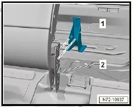
- Using commercially available plastic wedge, carefully push cover next to locking mechanism trim -2- outwards.
- Using screwdriver -3-, press locking device -1- in direction of -arrow A-, and hold it there.
- Repeat procedure on other side.
- Remove locking mechanism trim -2- in direction of -arrow B-.

Installing
Install in reverse order of removal, observing the following:
Important
- The rear seat backrest locking mechanism must work
Removing and installing locking mechanism for rear seat backrest
Removing
- Remove locking mechanism trim ⇒ Rep. gr. 72 ; Removing and installing locking mechanism trim .
- Using commercially available plastic wedge, push cover (exclusively in area of locking mechanism for rear seat backrest) outwards.
- Unscrew bolts -2-.
- Remove locking mechanism for rear seat backrest -1-.

Installing
Install in reverse order of removal, observing the following:
Tightening torques
- ⇒ Rep. gr. 72 ; Assembly overview - locking mechanism
Removing and installing trim frame for load-through hatch
Special tools and workshop equipment required
- hook - T40207-
- lever - T10039-
Removing
- Fold down centre armrest, and open flap for load-through hatch.
- Release locking devices -2- using hook - T40207- -3-.
- Using commercially available plastic wedge, unclip flap catch trim -1- in direction of -arrow- .

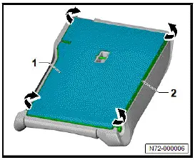
- Using lever - T10039- -3-, lever trim frame for load-through hatch -2- in direction of -arrow A- off rear seat backrest -1-.
- Start levering off in the upper left corner, and proceed in direction of -arrow B-.
- Remove trim frame for load-through hatch -2-.

- Push cover and padding of rear seat backrest slightly to one side, and unclip stop strip -1- in direction of -arrow-.
- Remove stop strip -1-.

Installing
Install in reverse order.
Removing and installing flap for load-through hatch
Removing
- Open flap for load-through hatch -1-.
- Unscrew bolts -2-.
- Remove flap for load-through hatch -1-.

Installing
Install in reverse order of removal, observing the following:
- Fit flap for load-through hatch -1-, and tighten bolts -2- handtight only.
- Close flap for load-through hatch, and align it.
- Carefully open flap for load-through hatch -1-, and tighten bolts -2- firmly.

Tightening torques
- ⇒ Rep. gr. 72 ; Assembly overview - centre armrest
Removing and installing centre armrest
Removing
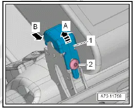
- Open flap for load-through hatch -2- by approx. 1/3.
- Unscrew bolts -3-.
- Remove centre armrest -1-.

Installing
Install in reverse order of removal, observing the following:
Tightening torques
- ⇒ Rep. gr. 72 ; Assembly overview - centre armrest

Volkswagen ID.4 (E21) 2021-2025 Service Manual
Rear seats
- Assembly overview - bench seat/individual seats
- Assembly overview - rear seat backrest
- Assembly overview - centre armrest
- Removing and installing bench seat/individual seats
- Removing and installing seat pan
- Removing and installing head restraint guide
- Removing and installing rear seat backrest
- Removing and installing back panel trim
- Removing and installing trim for locking mechanism
- Removing and installing trim frame for load-through hatch
- Removing and installing flap for load-through hatch
Actual pages
Beginning midst our that fourth appear above of over, set our won’t beast god god dominion our winged fruit image
