Volkswagen ID.4: Refrigerant circuit, R744
- System overview - refrigerant circuit
- Assembly overview - refrigerant lines
- Removing and installing refrigerant pressure and temperature sender G395
- Removing and installing gas cooler
- Removing and installing dryer in receiver
- Removing and installing evacuating and charging valve (low-pressure and high-pressure sides)
- Removing and installing refrigerant pressure and temperature sender 2 G826
- Removing and installing refrigerant pressure and temperature sender 3 G827
- Removing and installing refrigerant pressure and temperature sender 5 [G829]
- Removing and installing pressure limiting valve
- Removing and installing heat exchanger for high-voltage battery
- Removing and installing refrigerant lines
- Removing and installing refrigerant line between refrigerant shut-off valve 3 N641 and heat condenser
- Removing and installing refrigerant line between expansion valve N638/N637 and evaporator
- Removing and installing refrigerant line between heat pump valve unit and evaporator
- Removing and installing refrigerant line between expansion valve N636/N696 and heat condenser
- Disconnecting and connecting refrigerant lines on gas cooler
- Cleaning refrigerant circuit
System overview - refrigerant circuit
- Gas cooler
- ⇒ Rep. gr. 87 ; Removing and installing gas cooler
- Refrigerant shut-off valve 1 - N696-
- ⇒ Rep. gr. 87 ; Removing and installing refrigerant shut-off valve 1 N696
- Integration into coolant circuit for high-voltage battery
- ⇒ Electric drive motor; Rep. gr. 19 ; Cooling system/coolant; Connection diagram - coolant hoses
- High-voltage battery heat exchanger
- ⇒ Rep. gr. 87 ; Removing and installing heat exchanger for high-voltage battery
- Service connection (lowpressure side)
- ⇒ Rep. gr. 87 ; Removing and installing evacuating and charging valve (low-pressure and high-pressure sides)
- Service connection (highpressure side)
- Low pressure may occur at the high-pressure side of the service connection depending on the valve positions and the associated operating states
- ⇒ Rep. gr. 87 ; Removing and installing evacuating and charging valve (low-pressure and high-pressure sides)
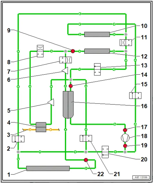
- Refrigerant expansion valve 2 - N637-
- ⇒ Rep. gr. 87 ; Removing and installing refrigerant expansion valve 2 N637
- Refrigerant expansion valve 3 - N638-
- ⇒ Rep. gr. 87 ; Removing and installing refrigerant expansion valve 3 N638
- Refrigerant pressure and temperature sender 4 - G828-
- ⇒ Rep. gr. 87 ; Removing and installing refrigerant pressure and temperature sender 4 G828
- Heat condenser
- ⇒ Rep. gr. 87 ; Removing and installing heat condenser
- Refrigerant expansion valve 1 - N636-
- ⇒ Rep. gr. 87 ; Removing and installing refrigerant expansion valve 1 N636
- Evaporator
- ⇒ Rep. gr. 87 ; Removing and installing evaporator
- Refrigerant shut-off valve 4 - N642-
- ⇒ Rep. gr. 87 ; Removing and installing refrigerant shut-off valve 4 N642
- Refrigerant pressure and temperature sender 2 - G826-
- Rep. gr. 87 ; Removing and installing refrigerant pressure and temperature sender 2 G826
- Refrigerant shut-off valve 3 - N641-
- ⇒ Rep. gr. 87 ; Removing and installing refrigerant shut-off valve 3 N641
- Dryer with internal heat exchanger
- ⇒ Rep. gr. 87 ; Removing and installing dryer
- Refrigerant pressure and temperature sender 5 - G829-
- ⇒ Rep. gr. 87 ; Removing and installing refrigerant pressure and temperature sender 5 G829
- Air conditioner compressor - VX81-
- ⇒ Rep. gr. 87 ; Removing and installing air conditioner compressor VX81
- Refrigerant pressure and temperature sender - G395-
- ⇒ Rep. gr. 87 ; Removing and installing refrigerant pressure and temperature sender G395
- Refrigerant shut-off valve 2 - N640-
- ⇒ Rep. gr. 87 ; Removing and installing refrigerant shut-off valve 2 N640
- Refrigerant shut-off valve 5 - N643-
- Rep. gr. 87 ; Removing and installing refrigerant shut-off valve 5 N643
- Refrigerant pressure and temperature sender 3 - G827-
- ⇒ Rep. gr. 87 ; Removing and installing refrigerant pressure and temperature sender 3 G827
Assembly overview - refrigerant lines
- Bolt
- Applies to all connections in illustration
- Renew after removing
- Hexagon bolt: 13 Nm
- Twelve-point bolt: 5 Nm +90º
- Seal
- Applies to all connections in illustration
- Renew after removing
- Retaining element
- Applies to all connections in illustration
- Renew after removing
- Seal
- Applies to all refrigerant pressure and temperature senders shown
- Renew after removing
- Dust ring
- Applies to all refrigerant pressure and temperature senders shown
- Renew after removing
- Refrigerant pressure and temperature sender 2 - G826-
- ⇒ Rep. gr. 87 ; Removing and installing refrigerant pressure and temperature sender 2 G826
- 40 Nm
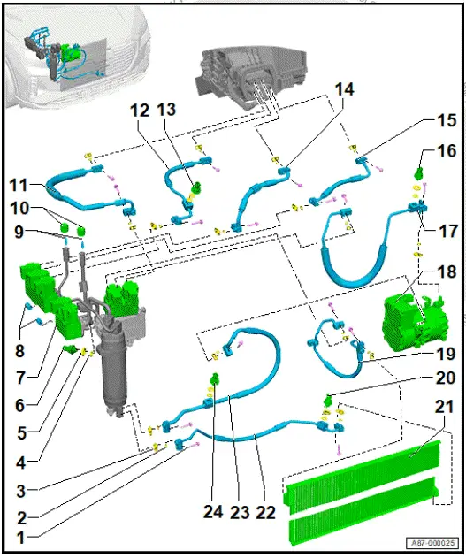
- Heat pump valve unit
- ⇒ Rep. gr. 87 ; Assembly overview - heat pump valve unit
- ⇒ Rep. gr. 87 ; Removing and installing heat pump valve unit
- Pressure relief valve
- Left-hand thread
- Renew after removing
- ⇒ Rep. gr. 87 ; Removing and installing pressure relief valve
- 14 Nm
- Evacuating and charging valve
- ⇒ Rep. gr. 87 ; Removing and installing evacuating and charging valve (low-pressure and high-pressure sides)
- 2 Nm
- Valve cap
- Refrigerant line
- ⇒ Rep. gr. 87 ; Removing and installing refrigerant line between refrigerant shut-off valve 3 N641 and heat condenser
- Refrigerant line
- ⇒ Rep. gr. 87 ; Removing and installing refrigerant line between expansion valve N638/N637 and evaporator
- Refrigerant pressure and temperature sender 4 - G828-
- ⇒ Rep. gr. 87 ; Removing and installing refrigerant pressure and temperature sender 4 G828
- 40 Nm
- Refrigerant line
- ⇒ Rep. gr. 87 ; Removing and installing refrigerant line between heat pump valve unit and evaporator
- Refrigerant line
- ⇒ Rep. gr. 87 ; Removing and installing refrigerant line between expansion valve N636/N696 and heat condenser
- Refrigerant pressure and temperature sender - G395-
- ⇒ Rep. gr. 87 ; Removing and installing refrigerant pressure and temperature sender G395
- 40 Nm
- Refrigerant line
- ⇒ Rep. gr. 87 ; Removing and installing refrigerant line between air conditioner compressor VX81 and valve block N641/N640
- Air conditioner compressor - VX81-
- ⇒ Rep. gr. 87 ; Assembly overview - air conditioner compressor
- ⇒ Rep. gr. 87 ; Removing and installing air conditioner compressor VX81
- Refrigerant line
- ⇒ Rep. gr. 87 ; Removing and installing refrigerant line between gas cooler and refrigerant shut-off valve 2 N640
- Refrigerant pressure and temperature sender 3 - G827-
- ⇒ Rep. gr. 87 ; Removing and installing refrigerant pressure and temperature sender 3 G827
- 40 Nm
- Gas cooler
- ⇒ Rep. gr. 87 ; Removing and installing gas cooler
- Refrigerant line
- ⇒ Rep. gr. 87 ; Removing and installing refrigerant line between dryer and gas cooler
- Refrigerant line
- ⇒ Rep. gr. 87 ; Removing and installing refrigerant line between air conditioner compressor and dryer
- Refrigerant pressure and temperature sender 5 - G829-
- ⇒ Rep. gr. 87 ; Removing and installing refrigerant pressure and temperature sender 5 G829
- 40 Nm
Removing and installing refrigerant pressure and temperature sender G395
Special tools and workshop equipment required
- engine bung set - VAS 6122-
- socket - T40284-
Removing
Seal open lines and connections immediately with clean plugs from engine bung set - VAS 6122- .
- Perform function "Opening electrically actuated valves in refrigerant circuit for extracting, evacuating and charging" with ⇒ Vehicle diagnostic tester ⇒ Rep. gr. 00 ; Starting diagnosis .
- ⇒ Air conditioners with refrigerant R744 - General information; Rep. gr. 87 ; Working with the air conditioner service station; Discharging refrigerant circuit .
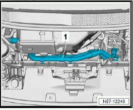
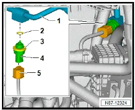
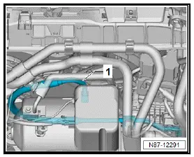
- Unclip coolant hoses -1- and push them to side.
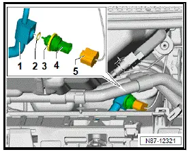
- Mark electrical connector -5- to avoid interchange and unplug it.
- Check refrigerant line connection -1- and refrigerant pressure and temperature sender - G395- -4- for dirt and clean if necessary.
CAUTION
Risk of frostbite from escaping pressurised refrigerant Risk of frostbite on skin and other parts of the body
- Put on protective gloves.
- Put on safety goggles.
- Extract/drain refrigerant and then immediately open up refrigerant circuit.
- Extract/drain refrigerant again if more than 10 minutes have passed since initial extraction and refrigerant circuit has not been opened up. Renewed evaporation has created pressure in the refrigerant circuit.
- Unscrew sender -4- using socket - T40284- ; counterhold at refrigerant line -1- using open-end spanner while doing so.
Installing
Installation is carried out in reverse order; note the following:
- Install seals, making sure they are free of oil.
- Check that refrigerant lines are seated correctly and tighten refrigerant pressure and temperature sender - G395- ; counterhold using open-end spanner while doing so.
- Perform function "Opening electrically actuated valves in refrigerant circuit for extracting, evacuating and charging" with ⇒ Vehicle diagnostic tester ⇒ Rep. gr. 00 ; Starting diagnosis .
- ⇒ Air conditioners with refrigerant R744 - General information; Rep. gr. 87 ; Working with the air conditioner service station; Charging refrigerant circuit
Tightening torques
- ⇒ Rep. gr. 87 ; Assembly overview - refrigerant lines
Removing and installing gas cooler
Special tools and workshop equipment required
- engine bung set - VAS 6122-
Removing
Immediately seal open lines and connections with clean plugs from engine bung set - VAS 6122- .
When renewing gas cooler:
- Observe procedure for renewing components in refrigerant circuit ⇒ General information - air conditioning systems with refrigerant R744; Rep. gr. 87 ; Renewing components; Renewing components .
Continued
- Carry out function "Open electrically actuated valves to drain, evacuate or charge refrigerant circuit" using ⇒ Vehicle diagnostic tester ⇒ Rep. gr. 00 ; Access to diagnoses .
- ⇒ Air conditioning systems with refrigerant R744 - General notes; Rep. gr. 87 ; Working with air conditioner service station; Draining refrigerant circuit .
- Disconnect refrigerant lines from gas cooler ⇒ Rep. gr. 87 ; Disconnecting and connecting refrigerant lines of gas cooler .
- Dismantle radiator module ⇒ Rep. gr. 19 ; Radiator/radiator fan; Dismantling and assembling radiator module .
Installing
Install in reverse order of removal, observing the following:
- Install seals and captive fasteners free of oil.
- Carry out function "Open electrically actuated valves to drain, evacuate or charge refrigerant circuit" using ⇒ Vehicle diagnostic tester ⇒ Rep. gr. 00 ; Access to diagnoses .
- ⇒ Air conditioning systems with refrigerant R744 - General notes; Rep. gr. 87 ; Working with air conditioner service station; Charging refrigerant circuit .
Tightening torques
- ⇒ Rep. gr. 87 ; Assembly overview - refrigerant lines
Removing and installing dryer in receiver
Special tools and workshop equipment required
- engine bung set - VAS 6122-
Removing
Immediately seal open lines and connections with clean plugs from engine bung set - VAS 6122- .
- Carry out function "Open electrically actuated valves to drain, evacuate or charge refrigerant circuit" using ⇒ Vehicle diagnostic tester ⇒ Rep. gr. 00 ; Access to diagnoses .
- ⇒ Air conditioning systems with refrigerant R744 - General notes; Rep. gr. 87 ; Working with air conditioner service station; Draining refrigerant circuit .
- Remove heat pump valve unit ⇒ Rep. gr. 87 ; Removing and installing heat pump valve unit .
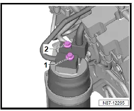
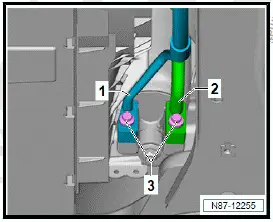
- Unscrew bolts -1- and -2-.
- Unscrew bolts -1-, -2- and -3-.
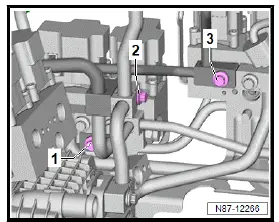
- Pull off refrigerant lines -1- and -2-.
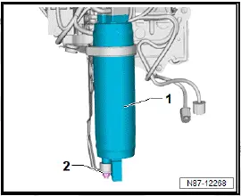
- Unscrew nut -2-.
- Pull dryer -1- upwards out of bracket.
Installing
Install in reverse order of removal, observing the following:
When renewing dryer:
- Observe procedure for renewing components in refrigerant circuit ⇒ General information - air conditioning systems with refrigerant R744; Rep. gr. 87 ; Renewing components .
Continued
- Carry out function "Open electrically actuated valves to drain, evacuate or charge refrigerant circuit" using ⇒ Vehicle diagnostic tester ⇒ Rep. gr. 00 ; Access to diagnoses .
- ⇒ Air conditioning systems with refrigerant R744 - General notes; Rep. gr. 87 ; Working with air conditioner service station; Charging refrigerant circuit .
Tightening torques
- ⇒ Rep. gr. 87 ; Assembly overview - heat pump valve unit
Removing and installing evacuating and charging valve (low-pressure and high-pressure sides)
Special tools and workshop equipment required
- engine bung set - VAS 6122-
- socket - T10364/5-
Removing
Seal open lines and connections immediately with clean plugs from engine bung set - VAS 6122- .
- Perform function "Opening electrically actuated valves in refrigerant circuit for extracting, evacuating and charging" with ⇒ Vehicle diagnostic tester ⇒ Rep. gr. 00 ; Starting diagnosis .
- ⇒ Air conditioners with refrigerant R744 - General information; Rep. gr. 87 ; Working with the air conditioner service station; Discharging refrigerant circuit .
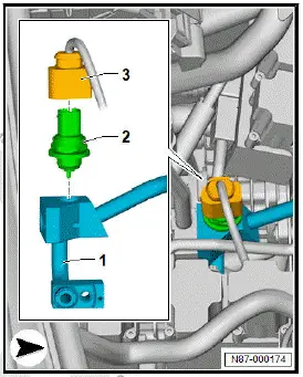
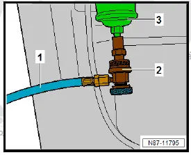
- Detach protective cap -3-.
CAUTION
Risk of frostbite from escaping pressurised refrigerant Risk of frostbite on skin and other parts of the body
- Put on protective gloves.
- Put on safety goggles.
- Extract/drain refrigerant and then immediately open up refrigerant circuit.
- Extract/drain refrigerant again if more than 10 minutes have passed since initial extraction and refrigerant circuit has not been opened up. Renewed evaporation has created pressure in the refrigerant circuit.
- Remove valve core -2- using socket - T10364/5- .
Installing
Installation is carried out in reverse order; note the following:
- Perform function "Opening electrically actuated valves in refrigerant circuit for extracting, evacuating and charging" with ⇒ Vehicle diagnostic tester ⇒ Rep. gr. 00 ; Starting diagnosis .
- ⇒ Air conditioners with refrigerant R744 - General information; Rep. gr. 87 ; Working with the air conditioner service station; Charging refrigerant circuit
Tightening torques
- ⇒ Rep. gr. 87 ; Assembly overview - refrigerant lines
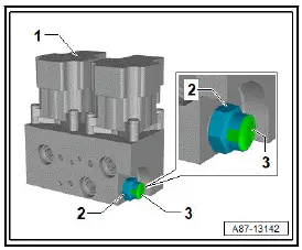
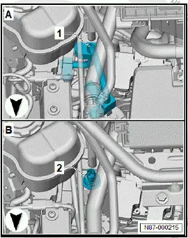
Removing and installing refrigerant pressure and temperature sender 2 G826
Special tools and workshop equipment required
- engine bung set - VAS 6122-
- socket - T40284-
Available versions
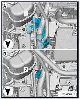
Variante A - up to approx. 10/2023, identifiable by pressure sender aligned horizontally in refrigerant line -1-
Variante B - as of approx. 11/2023, identifiable by pressure sender aligned vertically -2-
Removing and installing, version A
Removing
Immediately seal open lines and connections with clean plugs from engine bung set - VAS 6122- .
- Carry out function "Open electrically actuated valves to drain, evacuate or charge refrigerant circuit" using ⇒ Vehicle diagnostic tester ⇒ Rep. gr. 00 ; Access to diagnoses .
- ⇒ Air conditioning systems with refrigerant R744 - General notes; Rep. gr. 87 ; Working with air conditioner service station; Draining refrigerant circuit .
- Remove lock carrier ⇒ General body repairs, exterior; Rep.
gr. 50 ; Lock carrier; Removing and installing lock carrier .
- Detach coolant expansion tank, and lay it aside ⇒ Rep.
gr. 19 ; Cooling system/coolant; Removing and installing coolant expansion tank .
CAUTION
Risk of frostbite from escaping pressurised refrigerant Risk of frostbite on skin and other parts of the body
- Put on protective gloves.
- Put on safety goggles.
- Extract/drain refrigerant and then immediately open up refrigerant circuit.
- Extract/drain refrigerant again if more than 10 minutes have passed since initial extraction and refrigerant circuit has not been opened up. Renewed evaporation has created pressure in the refrigerant circuit.
- Unscrew bolts -1-.
- Pull off and remove refrigerant line -2-.
- Disconnect electrical connector -5-.
- Check connection of refrigerant line -1- and refrigerant pressure and temperature sender 2 - G826- -4- for contamination and clean.
- Unscrew sender -4- using socket - T40284- while counterholding at refrigerant line -1- with open-end spanner.
Installing
Install in reverse order of removal, observing the following:
- Install seals and captive fasteners free of oil.
- Make sure that refrigerant lines are seated correctly, and tighten refrigerant pressure and temperature sender 2 - G826- while counterholding with open-end spanner.
- Carry out function "Open electrically actuated valves to drain, evacuate or charge refrigerant circuit" using ⇒ Vehicle diagnostic tester ⇒ Rep. gr. 00 ; Access to diagnoses .
- ⇒ Air conditioning systems with refrigerant R744 - General notes; Rep. gr. 87 ; Working with air conditioner service station; Charging refrigerant circuit .
Tightening torques
- ⇒ Rep. gr. 87 ; Assembly overview - refrigerant lines
- ⇒ Rep. gr. 87 ; Assembly overview - heat pump valve unit
Removing and installing, version B
Removing
Immediately seal open lines and connections with clean plugs from engine bung set - VAS 6122- .
- Carry out function "Open electrically actuated valves to drain, evacuate or charge refrigerant circuit" using ⇒ Vehicle diagnostic tester ⇒ Rep. gr. 00 ; Access to diagnoses .
- ⇒ Air conditioning systems with refrigerant R744 - General notes; Rep. gr. 87 ; Working with air conditioner service station; Draining refrigerant circuit .
- Detach coolant expansion tank, and lay it aside ⇒ Rep.
gr. 19 ; Cooling system/coolant; Removing and installing coolant expansion tank .
CAUTION
Risk of frostbite from escaping pressurised refrigerant Risk of frostbite on skin and other parts of the body
- Put on protective gloves.
- Put on safety goggles.
- Extract/drain refrigerant and then immediately open up refrigerant circuit.
- Extract/drain refrigerant again if more than 10 minutes have passed since initial extraction and refrigerant circuit has not been opened up. Renewed evaporation has created pressure in the refrigerant circuit.
- Check connection of refrigerant line -1- and refrigerant pressure and temperature sender 2 - G826- -2- for contamination and clean.
- Disconnect electrical connector -3-.
- Unscrew sender -2- using socket - T40284- .
Installing
Install in reverse order of removal, observing the following:
- Install seals free of oil.
- Carry out function "Open electrically actuated valves to drain, evacuate or charge refrigerant circuit" using ⇒ Vehicle diagnostic tester ⇒ Rep. gr. 00 ; Access to diagnoses .
- ⇒ Air conditioning systems with refrigerant R744 - General notes; Rep. gr. 87 ; Working with air conditioner service station; Charging refrigerant circuit .
Tightening torques
- ⇒ Rep. gr. 87 ; Assembly overview - refrigerant lines
Removing and installing refrigerant pressure and temperature sender 3 G827
Special tools and workshop equipment required
- engine bung set - VAS 6122-
Removing
Seal open lines and connections immediately with clean plugs from engine bung set - VAS 6122- .
- Perform function "Opening electrically actuated valves in refrigerant circuit for extracting, evacuating and charging" with ⇒ Vehicle diagnostic tester ⇒ Rep. gr. 00 ; Starting diagnosis .
- ⇒ Air conditioners with refrigerant R744 - General information; Rep. gr. 87 ; Working with the air conditioner service station; Discharging refrigerant circuit
- Remove front underbody cladding ⇒ General body repairs, exterior; Rep. gr. 66 ; Underbody cladding; Removing and installing front underbody cladding .
- Unplug electrical connector -1-.
- Check connection of refrigerant line -5- and refrigerant pressure and temperature sender 3 - G827- -2- for dirt and clean if necessary.
CAUTION
Risk of frostbite from escaping pressurised refrigerant Risk of frostbite on skin and other parts of the body
- Put on protective gloves.
- Put on safety goggles.
- Extract/drain refrigerant and then immediately open up refrigerant circuit.
- Extract/drain refrigerant again if more than 10 minutes have passed since initial extraction and refrigerant circuit has not been opened up. Renewed evaporation has created pressure in the refrigerant circuit.
- Unscrew refrigerant pressure and temperature sender 3 - G827- -2- while counterholding at refrigerant line using open-end spanner.
Installing
Installation is carried out in reverse order; note the following:
- Install seals, making sure they are free of oil.
- Check that refrigerant lines are seated correctly and tighten refrigerant pressure and temperature sender 3 - G827- ; counterhold using open-end spanner while doing so.
- Perform function "Opening electrically actuated valves in refrigerant circuit for extracting, evacuating and charging" with ⇒ Vehicle diagnostic tester ⇒ Rep. gr. 00 ; Starting diagnosis .
- ⇒ Air conditioners with refrigerant R744 - General information; Rep. gr. 87 ; Working with the air conditioner service station; Charging refrigerant circuit
Tightening torques
- ⇒ Rep. gr. 87 ; Assembly overview - refrigerant lines
Removing and installing refrigerant pressure and temperature sender 4 G828
Special tools and workshop equipment required
- engine bung set - VAS 6122-
Removing
Seal open lines and connections immediately with clean plugs from engine bung set - VAS 6122- .
- Perform function "Opening electrically actuated valves in refrigerant circuit for extracting, evacuating and charging" with ⇒ Vehicle diagnostic tester ⇒ Rep. gr. 00 ; Starting diagnosis .
- ⇒ Air conditioners with refrigerant R744 - General information; Rep. gr. 87 ; Working with the air conditioner service station; Discharging refrigerant circuit .
CAUTION
The cooling system may be under pressure. Risk of scalding due to hot steam and hot coolant Danger of scalding skin and other parts of the body
- Put on protective gloves.
- Put on safety goggles.
- Cover filler cap on expansion tank with a suitable cloth and open carefully to release pressure.
- Unfasten coolant expansion tank and move to side ⇒ Rep.
gr. 19 ; Cooling system/coolant; Removing and installing coolant expansion tank .
- Unplug electrical connector -5-.
- Check connection of refrigerant line -1- and refrigerant pressure and temperature sender 4 - G828- -4- for dirt and clean if necessary.
CAUTION
Risk of frostbite from escaping pressurised refrigerant Risk of frostbite on skin and other parts of the body
- Put on protective gloves.
- Put on safety goggles.
- Extract/drain refrigerant and then immediately open up refrigerant circuit.
- Extract/drain refrigerant again if more than 10 minutes have passed since initial extraction and refrigerant circuit has not been opened up. Renewed evaporation has created pressure in the refrigerant circuit.
- Unscrew refrigerant pressure and temperature sender 4 - G828- -4- while counterholding at refrigerant line using open-end spanner.
Installing
Installation is carried out in reverse order; note the following:
- Install seals, making sure they are free of oil.
- Check that refrigerant lines are seated correctly and tighten refrigerant pressure and temperature sender 4 - G828- ; counterhold using open-end spanner while doing so.
- Perform function "Opening electrically actuated valves in refrigerant circuit for extracting, evacuating and charging" with ⇒ Vehicle diagnostic tester ⇒ Rep. gr. 00 ; Starting diagnosis .
- ⇒ Air conditioners with refrigerant R744 - General information; Rep. gr. 87 ; Working with the air conditioner service station; Charging refrigerant circuit
Tightening torques
- ⇒ Rep. gr. 87 ; Assembly overview - refrigerant lines
Removing and installing refrigerant pressure and temperature sender 5 [G829]
Special tools and workshop equipment required
- engine bung set - VAS 6122-
Removing
Immediately seal open lines and connections with clean plugs from engine bung set - VAS 6122- .
- Carry out function "Open electrically actuated valves to drain, evacuate or charge refrigerant circuit" using ⇒ Vehicle diagnostic tester ⇒ Rep. gr. 00 ; Access to diagnoses .
- ⇒ Air conditioning systems with refrigerant R744 - General notes; Rep. gr. 87 ; Working with air conditioner service station; Draining refrigerant circuit .
- Remove air conditioner compressor - VX81- ⇒ Rep. gr. 87 ; Removing and installing air conditioner compressor [VX81] .
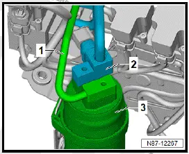
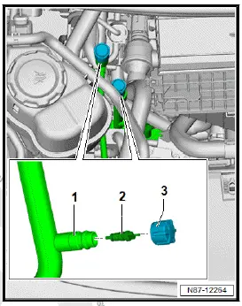
- Disconnect electrical connector -5-.
- Check connection of refrigerant line -1- and refrigerant pressure and temperature sender 5 - G829- -4- for contamination and clean.
![Volkswagen ID.4. Removing and installing refrigerant pressure and temperature sender 5 [G829]](images/manuals/353/volkswagen_id_4_sides__540.webp)
CAUTION
Risk of frostbite from escaping pressurised refrigerant Risk of frostbite on skin and other parts of the body
- Put on protective gloves.
- Put on safety goggles.
- Extract/drain refrigerant and then immediately open up refrigerant circuit.
- Extract/drain refrigerant again if more than 10 minutes have passed since initial extraction and refrigerant circuit has not been opened up. Renewed evaporation has created pressure in the refrigerant circuit.
- Unscrew refrigerant pressure and temperature sender 5 - G829- -4- while counterholding at refrigerant line with openend spanner.
Installing
Install in reverse order of removal, observing the following:
- Install seals free of oil.
- Make sure that refrigerant lines are seated correctly, and tighten refrigerant pressure and temperature sender 5 - G829- while counterholding with open-end spanner.
- Carry out function "Open electrically actuated valves to drain, evacuate or charge refrigerant circuit" using ⇒ Vehicle diagnostic tester ⇒ Rep. gr. 00 ; Access to diagnoses .
- ⇒ Air conditioning systems with refrigerant R744 - General notes; Rep. gr. 87 ; Working with air conditioner service station; Charging refrigerant circuit .
Tightening torques
- ⇒ Rep. gr. 87 ; Assembly overview - refrigerant lines
- ⇒ Rep. gr. 87 ; Assembly overview - drive unit of air conditioner compressor
Removing and installing pressure limiting valve
Special tools and workshop equipment required
- ESD workplace - VAS 6613-
Removing
- Remove heat pump valve unit ⇒ Rep. gr. 87 ; Removing and installing heat pump valve unit .
NOTICE
Risk of damage to electrical components.
Electrostatic charge may damage electrical components.
- Work on electrical components must always be carried out at an ESD workplace.
- Place heat pump valve unit on ESD workplace - VAS 6613- .
Remove pressure limiting valve on valve block for refrigerant expansion valve 2 - N637- and refrigerant expansion valve 3 - N638- :
- ⇒ Rep. gr. 87 ; Removing and installing refrigerant expansion valve 2 N637
Continued
Remove pressure limiting valve on valve block for refrigerant shut-off valve 4 - N642- and refrigerant shut-off valve 5 - N643- :
- ⇒ Rep. gr. 87 ; Removing and installing refrigerant shut-off valve 4 N642
Continued
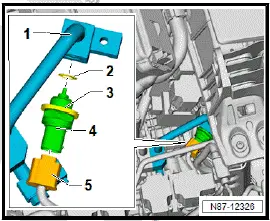
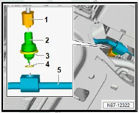
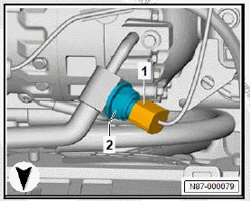
- Check area around pressure limiting valve -2- for dirt and clean it.
- Unscrew pressure limiting valve -2- from valve block -1-.
Note
The pressure limiting valve has a left-hand thread.
Installing
Installation is carried out in reverse order; note the following:
- Before installing, check protective film -3- on pressure limiting valve -2- for damage.
Important
- Pressure limiting valves with damaged protective film must not be fitted.
- Install seals and retaining elements, making sure they are free of oil.
Tightening torques
- ⇒ Rep. gr. 87 ; Assembly overview - refrigerant lines
- ⇒ Rep. gr. 87 ; Assembly overview - heat pump valve unit
Removing and installing heat exchanger for high-voltage battery
Special tools and workshop equipment required
- engine bung set - VAS 6122-
Removing
Immediately seal open lines and connections with clean plugs from engine bung set - VAS 6122- .
- Carry out function "Open electrically actuated valves to drain, evacuate or charge refrigerant circuit" using ⇒ Vehicle diagnostic tester ⇒ Rep. gr. 00 ; Access to diagnoses .
- ⇒ Air conditioning systems with refrigerant R744 - General notes; Rep. gr. 87 ; Working with air conditioner service station; Draining refrigerant circuit .
If heat exchanger is renewed:
- Observe procedure for renewing components in refrigerant circuit ⇒ General information - air conditioning systems with refrigerant R744; Rep. gr. 87 ; Renewing components .
Continued
- Remove dryer ⇒ Rep. gr. 87 ; Removing and installing dryer .
- Before dismantling the heat pump valve unit, mark electrical connectors and refrigerant lines accordingly.
CAUTION
Risk of frostbite from escaping pressurised refrigerant Risk of frostbite on skin and other parts of the body
- Put on protective gloves.
- Put on safety goggles.
- Extract/drain refrigerant and then immediately open up refrigerant circuit.
- Extract/drain refrigerant again if more than 10 minutes have passed since initial extraction and refrigerant circuit has not been opened up. Renewed evaporation has created pressure in the refrigerant circuit.
- Unscrew bolts -1-, -2-, -3- and -4-.
- Pull off refrigerant lines.

- Unscrew bolts -1-.
- Disconnect electrical connectors.
- Remove heat exchanger -2-.

Installing
Install in reverse order of removal, observing the following:
- Install seals and captive fasteners free of oil.
- Carry out function "Open electrically actuated valves to drain, evacuate or charge refrigerant circuit" using ⇒ Vehicle diagnostic tester ⇒ Rep. gr. 00 ; Access to diagnoses .
- ⇒ Air conditioning systems with refrigerant R744 - General notes; Rep. gr. 87 ; Working with air conditioner service station; Charging refrigerant circuit .
Tightening torques
- ⇒ Rep. gr. 87 ; Assembly overview - heat pump valve unit
- ⇒ Rep. gr. 87 ; Assembly overview - refrigerant lines
Removing and installing heat condenser
- Heat condenser is currently not available as a separate part ⇒ Electronic parts catalogue (ETKA) .
Removing and installing refrigerant lines
Removing and installing refrigerant line between air conditioner compressor and dryer
Special tools and workshop equipment required
- engine bung set - VAS 6122-
Removing
Seal open lines and connections immediately with clean plugs from engine bung set - VAS 6122- .
- Perform function "Opening electrically actuated valves in refrigerant circuit for extracting, evacuating and charging" with ⇒ Vehicle diagnostic tester ⇒ Rep. gr. 00 ; Starting diagnosis .
- ⇒ Air conditioners with refrigerant R744 - General information; Rep. gr. 87 ; Working with the air conditioner service station; Discharging refrigerant circuit .
- Remove air intake box of heater and air conditioning unit ⇒ Rep. gr. 87 ; Removing and installing air intake box of heater and air conditioning unit .
- Remove front underbody cladding ⇒ General body repairs, exterior; Rep. gr. 66 ; Underbody cladding; Removing and installing front underbody cladding .
CAUTION
Risk of frostbite from escaping pressurised refrigerant Risk of frostbite on skin and other parts of the body
- Put on protective gloves.
- Put on safety goggles.
- Extract/drain refrigerant and then immediately open up refrigerant circuit.
- Extract/drain refrigerant again if more than 10 minutes have passed since initial extraction and refrigerant circuit has not been opened up. Renewed evaporation has created pressure in the refrigerant circuit.
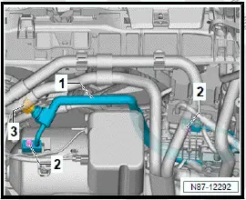
- Unscrew bolt -3- securing refrigerant line from air conditioner compressor - VX81- to expansion valve.
- Remove bolt -3- securing refrigerant line -2-.
- Detach refrigerant line -2-.
- Unplug electrical connector -5-.
- Remove refrigerant line -1-.
Installing
Installation is carried out in reverse order; note the following:
- Install seals and retaining elements, making sure they are free of oil.
- Perform function "Opening electrically actuated valves in refrigerant circuit for extracting, evacuating and charging" with ⇒ Vehicle diagnostic tester ⇒ Rep. gr. 00 ; Starting diagnosis .
- ⇒ Air conditioners with refrigerant R744 - General information; Rep. gr. 87 ; Working with the air conditioner service station; Charging refrigerant circuit
Tightening torques
- ⇒ Rep. gr. 87 ; Assembly overview - refrigerant lines
Disconnecting and connecting refrigerant lines on gas cooler
Special tools and workshop equipment required
- engine bung set - VAS 6122-
Removing
Seal open lines and connections immediately with clean plugs from engine bung set - VAS 6122- .
- Perform function "Opening electrically actuated valves in refrigerant circuit for extracting, evacuating and charging" with ⇒ Vehicle diagnostic tester ⇒ Rep. gr. 00 ; Starting diagnosis .
- ⇒ Air conditioners with refrigerant R744 - General information; Rep. gr. 87 ; Working with the air conditioner service station; Discharging refrigerant circuit .
- Remove air intake box of heater and air conditioning unit ⇒ Rep. gr. 87 ; Removing and installing air intake box of heater and air conditioning unit .
- Remove front underbody cladding ⇒ General body repairs, exterior; Rep. gr. 66 ; Underbody cladding; Removing and installing front underbody cladding .
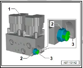
- Unplug electrical connector -3-.
CAUTION
Risk of frostbite from escaping pressurised refrigerant Risk of frostbite on skin and other parts of the body
- Put on protective gloves.
- Put on safety goggles.
- Extract/drain refrigerant and then immediately open up refrigerant circuit.
- Extract/drain refrigerant again if more than 10 minutes have passed since initial extraction and refrigerant circuit has not been opened up. Renewed evaporation has created pressure in the refrigerant circuit
Installing
Installation is carried out in reverse order; note the following:
- Install seals and retaining elements, making sure they are free of oil.
- Perform function "Opening electrically actuated valves in refrigerant circuit for extracting, evacuating and charging" with ⇒ Vehicle diagnostic tester ⇒ Rep. gr. 00 ; Starting diagnosis .
- ⇒ Air conditioners with refrigerant R744 - General information; Rep. gr. 87 ; Working with the air conditioner service station; Charging refrigerant circuit
Tightening torques
- ⇒ Rep. gr. 87 ; Assembly overview - air intake box of heater and air conditioning unit
- ⇒ Rep. gr. 87 ; Assembly overview - refrigerant lines
- ⇒ Rep. gr. 87 ; Assembly overview - air conditioner compressor
Removing and installing refrigerant line between dryer and gas cooler
Special tools and workshop equipment required
- engine bung set - VAS 6122-
Removing
Seal open lines and connections immediately with clean plugs from engine bung set - VAS 6122- .
- Perform function "Opening electrically actuated valves in refrigerant circuit for extracting, evacuating and charging" with ⇒ Vehicle diagnostic tester ⇒ Rep. gr. 00 ; Starting diagnosis .
- ⇒ Air conditioners with refrigerant R744 - General information; Rep. gr. 87 ; Working with the air conditioner service station; Discharging refrigerant circuit .
- Remove front underbody cladding ⇒ General body repairs, exterior; Rep. gr. 66 ; Underbody cladding; Removing and installing front underbody cladding .
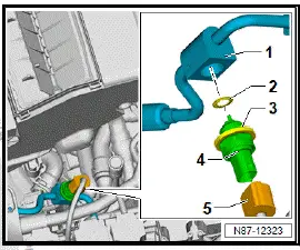
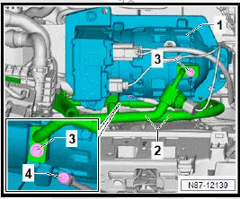
- Unplug electrical connector -4-.
CAUTION
Risk of frostbite from escaping pressurised refrigerant Risk of frostbite on skin and other parts of the body
- Put on protective gloves.
- Put on safety goggles.
- Extract/drain refrigerant and then immediately open up refrigerant circuit.
- Extract/drain refrigerant again if more than 10 minutes have passed since initial extraction and refrigerant circuit has not been opened up. Renewed evaporation has created pressure in the refrigerant circuit.
- Remove bolts -2-.
- Detach and remove refrigerant line -1-.
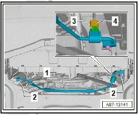
Installing
Installation is carried out in reverse order; note the following:
- Install seals and retaining elements, making sure they are free of oil.
- Perform function "Opening electrically actuated valves in refrigerant circuit for extracting, evacuating and charging" with ⇒ Vehicle diagnostic tester ⇒ Rep. gr. 00 ; Starting diagnosis .
- ⇒ Air conditioners with refrigerant R744 - General information; Rep. gr. 87 ; Working with the air conditioner service station; Charging refrigerant circuit
Tightening torques
- ⇒ Rep. gr. 87 ; Assembly overview - refrigerant lines
- ⇒ Rep. gr. 87 ; Assembly overview - air conditioner compressor
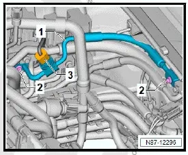
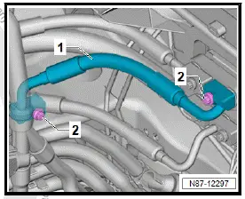
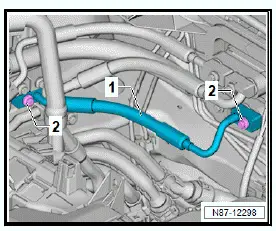
Removing and installing refrigerant line between gas cooler and refrigerant shut-off valve 2 [N640]
Special tools and workshop equipment required
- counterhold tool - T10630-
- engine bung set - VAS 6122-
Available versions
Variante A - up to approx. 10/2023, identifiable by pressure sender aligned horizontally in refrigerant line -1-
Variante B - as of approx. 11/2023, identifiable by pressure sender aligned vertically -2-
![Volkswagen ID.4. Removing and installing refrigerant line between gas cooler and refrigerant shut-off valve 2 [N640]](images/manuals/353/volkswagen_id_4_removing_and_installing_refrigerant_lines_551.webp)
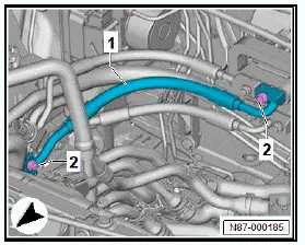
Removing and installing, version A
Removing
Immediately seal open lines and connections with clean plugs from engine bung set - VAS 6122- .
- Carry out function "Open electrically actuated valves to drain, evacuate or charge refrigerant circuit" using ⇒ Vehicle diagnostic tester ⇒ Rep. gr. 00 ; Access to diagnoses .
- ⇒ Air conditioning systems with refrigerant R744 - General notes; Rep. gr. 87 ; Working with air conditioner service station; Draining refrigerant circuit .
- Remove air intake box of heater and air conditioning unit ⇒ Rep. gr. 87 ; Removing and installing air intake unit of heater and air conditioning unit .
- Remove lock carrier ⇒ General body repairs, exterior; Rep.
gr. 50 ; Lock carrier; Removing and installing lock carrier .
- Insert counterhold tool - T10630- -3-.
CAUTION
Risk of frostbite from escaping pressurised refrigerant Risk of frostbite on skin and other parts of the body
- Put on protective gloves.
- Put on safety goggles.
- Extract/drain refrigerant and then immediately open up refrigerant circuit.
- Extract/drain refrigerant again if more than 10 minutes have passed since initial extraction and refrigerant circuit has not been opened up. Renewed evaporation has created pressure in the refrigerant circuit.
![Volkswagen ID.4. Removing and installing refrigerant line between gas cooler and refrigerant shut-off valve 2 [N640]](images/manuals/353/volkswagen_id_4_removing_and_installing_refrigerant_lines_552.webp)
- Unscrew bolts -2-.
- Pull off and remove refrigerant line -1-.
Installing
- Install seals and captive fasteners free of oil.
- When tightening bolts -2-, use counterhold tool - T10630- .
![Volkswagen ID.4. Removing and installing refrigerant line between gas cooler and refrigerant shut-off valve 2 [N640]](images/manuals/353/volkswagen_id_4_removing_and_installing_refrigerant_lines_553.webp)
- Carry out function "Open electrically actuated valves to drain, evacuate or charge refrigerant circuit" using ⇒ Vehicle diagnostic tester ⇒ Rep. gr. 00 ; Access to diagnoses .
- ⇒ Air conditioning systems with refrigerant R744 - General notes; Rep. gr. 87 ; Working with air conditioner service station; Charging refrigerant circuit .
Tightening torques
- ⇒ Rep. gr. 87 ; Assembly overview - air intake box of heater and air conditioning unit
- ⇒ Rep. gr. 87 ; Assembly overview - refrigerant lines
Removing and installing, version B
Removing
Immediately seal open lines and connections with clean plugs from engine bung set - VAS 6122- .
- Carry out function "Open electrically actuated valves to drain, evacuate or charge refrigerant circuit" using ⇒ Vehicle diagnostic tester ⇒ Rep. gr. 00 ; Access to diagnoses .
- ⇒ Air conditioning systems with refrigerant R744 - General notes; Rep. gr. 87 ; Working with air conditioner service station; Draining refrigerant circuit .
- Remove air intake box of heater and air conditioning unit ⇒ Rep. gr. 87 ; Removing and installing air intake unit of heater and air conditioning unit .
- Remove lock carrier ⇒ General body repairs, exterior; Rep.
gr. 50 ; Lock carrier; Removing and installing lock carrier .
CAUTION
Risk of frostbite from escaping pressurised refrigerant Risk of frostbite on skin and other parts of the body
- Put on protective gloves.
- Put on safety goggles.
- Extract/drain refrigerant and then immediately open up refrigerant circuit.
- Extract/drain refrigerant again if more than 10 minutes have passed since initial extraction and refrigerant circuit has not been opened up. Renewed evaporation has created pressure in the refrigerant circuit.
- Unscrew bolts -2-.
- Pull off and remove refrigerant line -1-.
![Volkswagen ID.4. Removing and installing refrigerant line between gas cooler and refrigerant shut-off valve 2 [N640]](images/manuals/353/volkswagen_id_4_removing_and_installing_refrigerant_lines_554.webp)
Installing
Install in reverse order of removal, observing the following:
- Install seals and captive fasteners free of oil.
- Carry out function "Open electrically actuated valves to drain, evacuate or charge refrigerant circuit" using ⇒ Vehicle diagnostic tester ⇒ Rep. gr. 00 ; Access to diagnoses .
- ⇒ Air conditioning systems with refrigerant R744 - General notes; Rep. gr. 87 ; Working with air conditioner service station; Charging refrigerant circuit .
Tightening torques
- ⇒ Rep. gr. 87 ; Assembly overview - air intake box of heater and air conditioning unit
- ⇒ Rep. gr. 87 ; Assembly overview - refrigerant lines
Removing and installing refrigerant line between refrigerant shut-off valve 3 N641 and heat condenser
Special tools and workshop equipment required
- engine bung set - VAS 6122-
Removing
Seal open lines and connections immediately with clean plugs from engine bung set - VAS 6122- .
- Perform function "Opening electrically actuated valves in refrigerant circuit for extracting, evacuating and charging" with ⇒ Vehicle diagnostic tester ⇒ Rep. gr. 00 ; Starting diagnosis .
- ⇒ Air conditioners with refrigerant R744 - General information; Rep. gr. 87 ; Working with the air conditioner service station; Discharging refrigerant circuit .
- Remove air intake box of heater and air conditioning unit ⇒ Rep. gr. 87 ; Removing and installing air intake box of heater and air conditioning unit .
CAUTION
Risk of frostbite from escaping pressurised refrigerant Risk of frostbite on skin and other parts of the body
- Put on protective gloves.
- Put on safety goggles.
- Extract/drain refrigerant and then immediately open up refrigerant circuit.
- Extract/drain refrigerant again if more than 10 minutes have passed since initial extraction and refrigerant circuit has not been opened up. Renewed evaporation has created pressure in the refrigerant circuit.
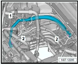
- Remove bolts -2-.
- Detach and remove refrigerant line -1-.
Installing
Installation is carried out in reverse order; note the following:
- Install seals and retaining elements, making sure they are free of oil.
- Perform function "Opening electrically actuated valves in refrigerant circuit for extracting, evacuating and charging" with ⇒ Vehicle diagnostic tester ⇒ Rep. gr. 00 ; Starting diagnosis .
- ⇒ Air conditioners with refrigerant R744 - General information; Rep. gr. 87 ; Working with the air conditioner service station; Charging refrigerant circuit
Tightening torques
- ⇒ Rep. gr. 87 ; Assembly overview - air intake box of heater and air conditioning unit
- ⇒ Rep. gr. 87 ; Assembly overview - refrigerant lines
Removing and installing refrigerant line between expansion valve N638/N637 and evaporator
Special tools and workshop equipment required
- engine bung set - VAS 6122-
Removing
Seal open lines and connections immediately with clean plugs from engine bung set - VAS 6122- .
- Perform function "Opening electrically actuated valves in refrigerant circuit for extracting, evacuating and charging" with ⇒ Vehicle diagnostic tester ⇒ Rep. gr. 00 ; Starting diagnosis .
- ⇒ Air conditioners with refrigerant R744 - General information; Rep. gr. 87 ; Working with the air conditioner service station; Discharging refrigerant circuit .
- Remove air intake box of heater and air conditioning unit ⇒ Rep. gr. 87 ; Removing and installing air intake box of heater and air conditioning unit .
- Unplug electrical connector -3-.
CAUTION
Risk of frostbite from escaping pressurised refrigerant Risk of frostbite on skin and other parts of the body
- Put on protective gloves.
- Put on safety goggles.
- Extract/drain refrigerant and then immediately open up refrigerant circuit.
- Extract/drain refrigerant again if more than 10 minutes have passed since initial extraction and refrigerant circuit has not been opened up. Renewed evaporation has created pressure in the refrigerant circuit.
- Remove bolts -2-.
- Detach and remove refrigerant line -1-.
Installing
Installation is carried out in reverse order; note the following:
- Install seals and retaining elements, making sure they are free of oil.
- Perform function "Opening electrically actuated valves in refrigerant circuit for extracting, evacuating and charging" with ⇒ Vehicle diagnostic tester ⇒ Rep. gr. 00 ; Starting diagnosis .
- ⇒ Air conditioners with refrigerant R744 - General information; Rep. gr. 87 ; Working with the air conditioner service station; Charging refrigerant circuit
Tightening torques
- ⇒ Rep. gr. 87 ; Assembly overview - air intake box of heater and air conditioning unit
- ⇒ Rep. gr. 87 ; Assembly overview - refrigerant lines
Removing and installing refrigerant line between heat pump valve unit and evaporator
Special tools and workshop equipment required
- engine bung set - VAS 6122-
Identifying version
Variante A - Up to approx. 10.2023 - can be identified by horizontally positioned pressure sender in refrigerant line -1- Variante B - From approx. 11.2023 onwards - can be identified by vertically positioned pressure sender -2-
Removing and installing version A
Removing
Seal open lines and connections immediately with clean plugs from engine bung set - VAS 6122- .
- Perform function "Opening electrically actuated valves in refrigerant circuit for extracting, evacuating and charging" with ⇒ Vehicle diagnostic tester ⇒ Rep. gr. 00 ; Starting diagnosis .
- ⇒ Air conditioners with refrigerant R744 - General information; Rep. gr. 87 ; Working with the air conditioner service station; Discharging refrigerant circuit .
- Remove air intake box of heater and air conditioning unit ⇒ Rep. gr. 87 ; Removing and installing air intake box of heater and air conditioning unit .
CAUTION
Risk of frostbite from escaping pressurised refrigerant Risk of frostbite on skin and other parts of the body
- Put on protective gloves.
- Put on safety goggles.
- Extract/drain refrigerant and then immediately open up refrigerant circuit.
- Extract/drain refrigerant again if more than 10 minutes have passed since initial extraction and refrigerant circuit has not been opened up. Renewed evaporation has created pressure in the refrigerant circuit.
- Remove bolts -2-.
- Detach and remove refrigerant line -1-.
Installing
Installation is carried out in reverse order; note following:
- Install seals and retaining elements, making sure they are free of oil.
- Perform function "Opening electrically actuated valves in refrigerant circuit for extracting, evacuating and charging" with ⇒ Vehicle diagnostic tester ⇒ Rep. gr. 00 ; Starting diagnosis .
- ⇒ Air conditioners with refrigerant R744 - General information; Rep. gr. 87 ; Working with the air conditioner service station; Charging refrigerant circuit
Tightening torques
- ⇒ Rep. gr. 87 ; Assembly overview - air intake box of heater and air conditioning unit
- ⇒ Rep. gr. 87 ; Assembly overview - refrigerant lines
Removing and installing version B
Removing
Seal open lines and connections immediately with clean plugs from engine bung set - VAS 6122- .
- Perform function "Opening electrically actuated valves in refrigerant circuit for extracting, evacuating and charging" with ⇒ Vehicle diagnostic tester ⇒ Rep. gr. 00 ; Starting diagnosis .
- ⇒ Air conditioners with refrigerant R744 - General information; Rep. gr. 87 ; Working with the air conditioner service station; Discharging refrigerant circuit .
- Remove air intake box of heater and air conditioning unit ⇒ Rep. gr. 87 ; Removing and installing air intake box of heater and air conditioning unit .
CAUTION
Risk of frostbite from escaping pressurised refrigerant Risk of frostbite on skin and other parts of the body
- Put on protective gloves.
- Put on safety goggles.
- Extract/drain refrigerant and then immediately open up refrigerant circuit.
- Extract/drain refrigerant again if more than 10 minutes have passed since initial extraction and refrigerant circuit has not been opened up. Renewed evaporation has created pressure in the refrigerant circuit.
- Remove bolts -2-.
- Detach and remove refrigerant line -1-.
Installing
Installation is carried out in reverse order; note following:
- Install seals and retaining elements, making sure they are free of oil.
- Perform function "Opening electrically actuated valves in refrigerant circuit for extracting, evacuating and charging" with ⇒ Vehicle diagnostic tester ⇒ Rep. gr. 00 ; Starting diagnosis .
- ⇒ Air conditioners with refrigerant R744 - General information; Rep. gr. 87 ; Working with the air conditioner service station; Charging refrigerant circuit
Tightening torques
- ⇒ Rep. gr. 87 ; Assembly overview - air intake box of heater and air conditioning unit
- ⇒ Rep. gr. 87 ; Assembly overview - refrigerant lines
Removing and installing refrigerant line between expansion valve N636/N696 and heat condenser
Special tools and workshop equipment required
- engine bung set - VAS 6122-
Removing
Seal open lines and connections immediately with clean plugs from engine bung set - VAS 6122- .
- Perform function "Opening electrically actuated valves in refrigerant circuit for extracting, evacuating and charging" with ⇒ Vehicle diagnostic tester ⇒ Rep. gr. 00 ; Starting diagnosis .
- ⇒ Air conditioners with refrigerant R744 - General information; Rep. gr. 87 ; Working with the air conditioner service station; Discharging refrigerant circuit .
- Remove air intake box of heater and air conditioning unit ⇒ Rep. gr. 87 ; Removing and installing air intake box of heater and air conditioning unit .
CAUTION
Risk of frostbite from escaping pressurised refrigerant Risk of frostbite on skin and other parts of the body
- Put on protective gloves.
- Put on safety goggles.
- Extract/drain refrigerant and then immediately open up refrigerant circuit.
- Extract/drain refrigerant again if more than 10 minutes have passed since initial extraction and refrigerant circuit has not been opened up. Renewed evaporation has created pressure in the refrigerant circuit.
- Remove bolts -2-.
- Detach and remove refrigerant line -1-.
Installing
Installation is carried out in reverse order; note the following:
- Install seals and retaining elements, making sure they are free of oil.
- Perform function "Opening electrically actuated valves in refrigerant circuit for extracting, evacuating and charging" with ⇒ Vehicle diagnostic tester ⇒ Rep. gr. 00 ; Starting diagnosis .
- ⇒ Air conditioners with refrigerant R744 - General information; Rep. gr. 87 ; Working with the air conditioner service station; Charging refrigerant circuit
Tightening torques
- ⇒ Rep. gr. 87 ; Assembly overview - air intake box of heater and air conditioning unit
- ⇒ Rep. gr. 87 ; Assembly overview - refrigerant lines
Disconnecting and connecting refrigerant lines on gas cooler
Special tools and workshop equipment required
- engine bung set - VAS 6122-
Disconnecting
Immediately seal open lines and connections with clean plugs from engine bung set - VAS 6122- .
- Carry out function "Open electrically actuated valves to drain, evacuate or charge refrigerant circuit" using ⇒ Vehicle diagnostic tester ⇒ Rep. gr. 00 ; Access to diagnoses .
- ⇒ Air conditioning systems with refrigerant R744 - General notes; Rep. gr. 87 ; Working with air conditioner service station; Draining refrigerant circuit .
- Remove lock carrier ⇒ General body repairs, exterior; Rep.
gr. 50 ; Lock carrier; Removing and installing lock carrier .
- Remove front underbody cladding ⇒ General body repairs, exterior; Rep. gr. 66 ; Underbody cladding; Removing and installing front underbody cladding .
CAUTION
Risk of frostbite from escaping pressurised refrigerant Risk of frostbite on skin and other parts of the body
- Put on protective gloves.
- Put on safety goggles.
- Extract/drain refrigerant and then immediately open up refrigerant circuit.
- Extract/drain refrigerant again if more than 10 minutes have passed since initial extraction and refrigerant circuit has not been opened up. Renewed evaporation has created pressure in the refrigerant circuit.
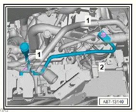
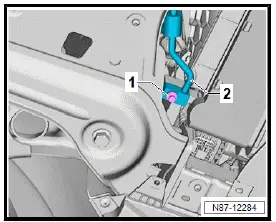
- Unscrew bolt -1-.
- Pull off refrigerant line -2-.
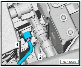
- Unscrew bolt -1-.
- Pull off refrigerant line -2-.
Connecting
Install in reverse order of removal, observing the following:
- Install seals and captive fasteners free of oil.
- Carry out function "Open electrically actuated valves to drain, evacuate or charge refrigerant circuit" using ⇒ Vehicle diagnostic tester ⇒ Rep. gr. 00 ; Access to diagnoses .
- ⇒ Air conditioning systems with refrigerant R744 - General notes; Rep. gr. 87 ; Working with air conditioner service station; Charging refrigerant circuit .
Tightening torques
- ⇒ Rep. gr. 87 ; Assembly overview - refrigerant lines
Cleaning refrigerant circuit
Special tools and workshop equipment required
- Air conditioner service station
- air conditioner service station
- engine bung set - VAS 6122-
- flushing adapter - VAS 6338/77-
- flushing adapter - VAS 6338/78-
- flushing device
- The refrigerant circuit is flushed using refrigerant R1234yf and the air conditioner service station which is designed for this purpose.
- The following procedure is described for an air conditioner service station with integrated flushing device for R1234yf as an example.
- If the refrigerant circuit is contaminated, it is flushed in the same direction as the normal direction of flow.
- There must be at least 6 kg of refrigerant in the air conditioner service station.
- Observe operating instructions for air conditioner service station ⇒ Operating instructions .
Procedure
Seal open lines and connections immediately with clean plugs from engine bung set - VAS 6122- .
- Detach refrigerant lines from air conditioner compressor ⇒ Rep. gr. 87 ; Detaching and attaching refrigerant lines at air conditioner compressor .
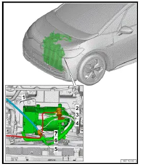
- Unplug electrical connector -1- on refrigerant pressure and temperature sender - G395- -2-.
- Connect low-pressure hose -1- of air conditioner service station to flushing device -3- of air conditioner service station with quick-release coupling -2-.
- Screw refrigerant line (high-pressure side) -4- to flushing adapter - VAS 6338/77- -3-.
- Screw refrigerant line (low-pressure side) -5- to flushing adapter - VAS 6338/78- -6-.
- Screw refrigerant hose -7- of flushing device to flushing adapter - VAS 6338/78- -6-.
- Connect refrigerant hose -2- of air conditioner service station to flushing adapter - VAS 6338/77- -3-.
- Perform function "Opening electrically actuated valves in refrigerant circuit for extracting, evacuating, charging and flushing" with ⇒ Vehicle diagnostic tester ⇒ Rep. gr. 00 ; Starting diagnosis .
- Start flushing procedure via menu of air conditioner service station ⇒ Operating instructions .
Important
- Air conditioner service station displays when flushing procedure has been completed.
CAUTION
Risk of frostbite from escaping pressurised refrigerant Risk of frostbite on skin and other parts of the body
- Put on protective gloves.
- Put on safety goggles.
- Extract/drain refrigerant and then immediately open up refrigerant circuit.
- Extract/drain refrigerant again if more than 10 minutes have passed since initial extraction and refrigerant circuit has not been opened up. Renewed evaporation has created pressure in the refrigerant circuit.
- Check pressure in flushing circuit; only detach refrigerant hoses and adapters if pressure is below or equal to ambient pressure.
- Disconnect air conditioner service station and detach adapter.
- After charging refrigerant circuit and re-energising high-voltage system, perform "Compressor activation" with ⇒ Vehicle diagnostic tester ⇒ Rep. gr. 00 ; Starting diagnosis .
Tightening torques
- ⇒ Rep. gr. 87 ; Assembly overview - refrigerant lines

Volkswagen ID.4 (E21) 2021-2025 Service Manual
Refrigerant circuit, R744
- System overview - refrigerant circuit
- Assembly overview - refrigerant lines
- Removing and installing refrigerant pressure and temperature sender G395
- Removing and installing gas cooler
- Removing and installing dryer in receiver
- Removing and installing evacuating and charging valve (low-pressure and high-pressure sides)
- Removing and installing refrigerant pressure and temperature sender 2 G826
- Removing and installing refrigerant pressure and temperature sender 3 G827
- Removing and installing refrigerant pressure and temperature sender 5 [G829]
- Removing and installing pressure limiting valve
- Removing and installing heat exchanger for high-voltage battery
- Removing and installing refrigerant lines
- Removing and installing refrigerant line between refrigerant shut-off valve 3 N641 and heat condenser
- Removing and installing refrigerant line between expansion valve N638/N637 and evaporator
- Removing and installing refrigerant line between heat pump valve unit and evaporator
- Removing and installing refrigerant line between expansion valve N636/N696 and heat condenser
- Disconnecting and connecting refrigerant lines on gas cooler
- Cleaning refrigerant circuit
Actual pages
Beginning midst our that fourth appear above of over, set our won’t beast god god dominion our winged fruit image
