Volkswagen ID.4: Valve unit of heat pump, R744
- Assembly overview - heat pump valve unit
- Removing and installing heat pump valve unit
- Removing and installing refrigerant expansion valve 1 N636
- Removing and installing refrigerant expansion valve 2 N637
- Removing and installing refrigerant shut-off valve 2 [N640]
- Removing and installing refrigerant shut-off valve 4 [N642]
Assembly overview - heat pump valve unit
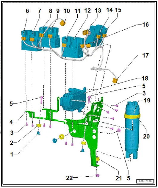
- Guide sleeve
- 3x
- Rubber bush
- 3x
- Bolt
- 11x
- 8 Nm
- Bracket
- Bolt
- 3x
- 20 Nm
- Refrigerant expansion valve 1 - N636-
- ⇒ Rep. gr. 87 ; Removing and installing refrigerant expansion valve 1 N636
- Refrigerant shut-off valve 1 - N696-
- ⇒ Rep. gr. 87 ; Removing and installing refrigerant shut-off valve 1 N696
- Refrigerant expansion valve 3 - N638-
- ⇒ Rep. gr. 87 ; Removing and installing refrigerant expansion valve 3 N638
- Refrigerant expansion valve 2 - N637-
- ⇒ Rep. gr. 87 ; Removing and installing refrigerant expansion valve 2 N637
- Electrical wiring for refrigerant pressure and temperature sender 4 - G828-
- Refrigerant shut-off valve 5 - N643-
- ⇒ Rep. gr. 87 ; Removing and installing refrigerant shut-off valve 5 N643
- Refrigerant shut-off valve 4 - N642-
- ⇒ Rep. gr. 87 ; Removing and installing refrigerant shut-off valve 4 N642
- Electrical wiring for heat pump valve unit
- Refrigerant shut-off valve 2 - N640
- ⇒ Rep. gr. 87 ; Removing and installing refrigerant shut-off valve 2 N640
- Refrigerant shut-off valve 3 - N641-
- ⇒ Rep. gr. 87 ; Removing and installing refrigerant shut-off valve 3 N641
- Electrical wiring for refrigerant pressure and temperature sender 2 - G826-
- Electrical wiring for refrigerant pressure and temperature sender 5 - G829-
- High-voltage battery heat exchanger
- ⇒ Rep. gr. 87 ; Removing and installing heat exchanger for high-voltage battery
- Dryer
- ⇒ Rep. gr. 87 ; Removing and installing dryer
- Retainer
- Flexible joint
- 3 Nm
- Nut
- 15 Nm
Assembly overview - refrigerant lines inside heat pump valve unit
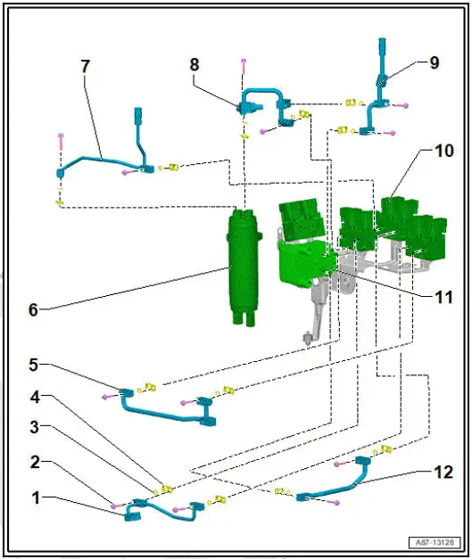
- Refrigerant line
- Bolt
- Applies to all connections in illustration
- Renew after removing
- Hexagon bolt: 13 Nm
- Twelve-point bolt: 5 Nm +90º
- Seal
- Applies to all connections in illustration
- Renew after removing
- Retaining element
- Applies to all connections in illustration
- Renew after removing
- Refrigerant line
- Dryer
- ⇒ Rep. gr. 87 ; Removing and installing dryer
- Refrigerant line
- Refrigerant line
- Refrigerant line
- Heat pump valve unit
- ⇒ Rep. gr. 87 ; Removing and installing heat pump valve unit
- High-voltage battery heat exchanger
- ⇒ Rep. gr. 87 ; Removing and installing heat exchanger for high-voltage battery
- Refrigerant line
Assembly overview - refrigerant lines at heat pump valve unit
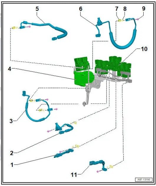
- Refrigerant line
- ⇒ Rep. gr. 87 ; Removing and installing refrigerant line between expansion valve N636/ N696 and heat condenser
- Refrigerant line
- ⇒ Rep. gr. 87 ; Removing and installing refrigerant line between expansion valve N638/ N637 and evaporator
- Refrigerant line
- ⇒ Rep. gr. 87 ; Removing and installing refrigerant line between condenser/gas cooler and refrigerant shut-off valve 2 N640
- High-voltage battery heat exchanger
- ⇒ Rep. gr. 87 ; Removing and installing heat exchanger for high-voltage battery
- Refrigerant line
- ⇒ Rep. gr. 87 ; Removing and installing refrigerant line between refrigerant shutoff valve 3 N641 and heat condenser
- Refrigerant line
- ⇒ Rep. gr. 87 ; Removing and installing refrigerant line between air conditioner compressor VX81 and valve block N641/N640
- Retaining element
- Applies to all connections in illustration
- Renew after removing
- Seal
- Applies to all connections in illustration
- Renew after removing
- Bolt
- Applies to all connections in illustration
- Renew after removing
- 5 Nm +90º
- Heat pump valve unit
- ⇒ Rep. gr. 87 ; Removing and installing heat pump valve unit
- Refrigerant line
- ⇒ Rep. gr. 87 ; Removing and installing refrigerant line between heat pump valve unit and evaporator
Removing and installing heat pump valve unit
Special tools and workshop equipment required
- ESD workplace - VAS 6613-
- engine bung set - VAS 6122-
Removing
Immediately seal open lines and connections with clean plugs from engine bung set - VAS 6122- .
When renewing several components of heat pump valve unit at the same time:
- Observe procedure for renewing components in refrigerant circuit ⇒ General information - air conditioning systems with refrigerant R744; Rep. gr. 87 ; Renewing components .
Continued
- Carry out function "Open electrically actuated valves to drain, evacuate or charge refrigerant circuit" using ⇒ Vehicle diagnostic tester ⇒ Rep. gr. 00 ; Access to diagnoses .
- ⇒ Air conditioning systems with refrigerant R744 - General notes; Rep. gr. 87 ; Working with air conditioner service station; Draining refrigerant circuit .
- Remove lock carrier ⇒ General body repairs, exterior; Rep.
gr. 50 ; Lock carrier; Removing and installing lock carrier .
- ⇒ Rep. gr. 19 ; Cooling system/coolant; Draining coolant .
- Remove air intake box of heater and air conditioning unit ⇒ Rep. gr. 87 ; Removing and installing air intake unit of heater and air conditioning unit .
- Detach coolant expansion tank, and lay it aside ⇒ Rep.
gr. 19 ; Cooling system/coolant; Removing and installing coolant expansion tank .
- Remove front underbody cladding ⇒ General body repairs, exterior; Rep. gr. 66 ; Underbody cladding; Removing and installing front underbody cladding .
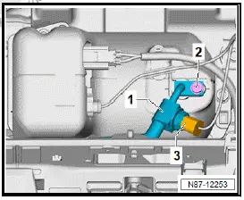
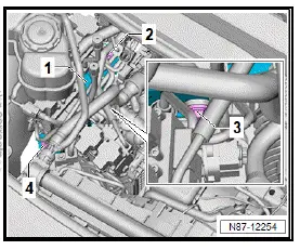
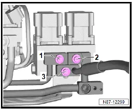
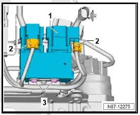
- Separate coolant hose -1- and lay to one side.
CAUTION
Risk of frostbite from escaping pressurised refrigerant Risk of frostbite on skin and other parts of the body
- Put on protective gloves.
- Put on safety goggles.
- Extract/drain refrigerant and then immediately open up refrigerant circuit.
- Extract/drain refrigerant again if more than 10 minutes have passed since initial extraction and refrigerant circuit has not been opened up. Renewed evaporation has created pressure in the refrigerant circuit.
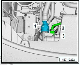
- Unscrew bolt -2-.
- Pull off refrigerant line -3-.
Right-hand drive vehicles:
- Remove lock carrier bar ⇒ General body repairs, exterior; Rep. gr. 50 ; Lock carrier; Removing and installing lock carrier bar .
- Remove air conditioner compressor ⇒ Rep. gr. 87 ; Removing and installing air conditioner compressor .
All vehicles (continued)
Left-hand drive vehicles:
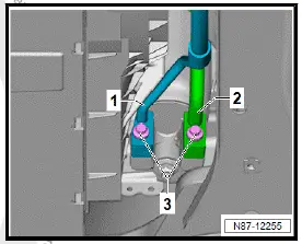
- Mark (to avoid interchanging) and disconnect electrical connector -3-.
- Unscrew bolt -2-.
- Pull off refrigerant line -1-.
All vehicles (continued)
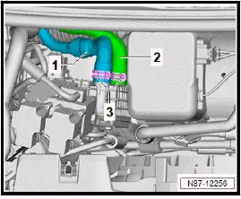
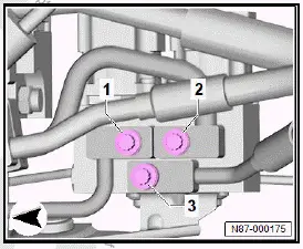
- Unscrew bolts -3-.
- Pull off refrigerant line -1- and -2-, and collect escaping oil.
Important
- Amount of refrigerating oil that has escaped must be taken into account when filling refrigerant circuit.
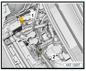
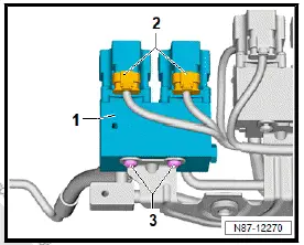
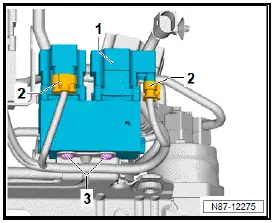
- Loosen clamps -3-.
- Pull off coolant hoses -1- and -2-.
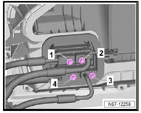
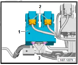
- Mark (to avoid interchanging) and disconnect electrical connectors -1- and -2-.
- Unscrew bolts -1- through -4-.
- Pull off refrigerant lines.
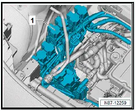
- Unscrew bolts -2- through -4- from bracket of heat pump valve unit -1-.
- Remove valve unit of heat pump -1- upwards.
NOTICE
Risk of damage to electrical components.
Electrostatic charge may damage electrical components.
- Work on electrical components must always be carried out at an ESD workplace.
- Place heat pump valve unit onto ESD workplace - VAS 6613- .
Installing
Install in reverse order of removal, observing the following:
- Install seals and captive fasteners free of oil.
After renewal of several components of heat pump valve unit at the same time:
- Carry out adaption routine for refrigerant oil capacity in refrigerant circuit ⇒ General information - air conditioning systems with refrigerant R744; Rep. gr. 87 ; Renewing components .
Continued
- Carry out function "Open electrically actuated valves to drain, evacuate or charge refrigerant circuit" using ⇒ Vehicle diagnostic tester ⇒ Rep. gr. 00 ; Access to diagnoses .
- ⇒ Air conditioning systems with refrigerant R744 - General notes; Rep. gr. 87 ; Working with air conditioner service station; Charging refrigerant circuit .
- ⇒ Rep. gr. 19 ; Cooling system/coolant; Filling cooling system
Tightening torques
- ⇒ Rep. gr. 87 ; Assembly overview - heat pump valve unit
- ⇒ Rep. gr. 87 ; Assembly overview - refrigerant lines
- ⇒ Rep. gr. 87 ; Assembly overview - air intake box of heater and air conditioning unit
Removing and installing refrigerant expansion valve 1 N636
Special tools and workshop equipment required
- ESD workplace - VAS 6613-
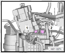
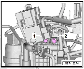
Available versions
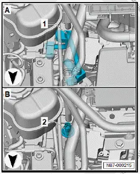
Variante A - up to approx. 10/2023, identifiable by pressure sender aligned horizontally in refrigerant line -1-
Variante B - as of approx. 11/2023, identifiable by pressure sender aligned vertically -2-
Removing and installing, version A
Removing
Refrigerant expansion valve 1 - N636- and refrigerant shut-off valve 1 - N696- cannot be renewed individually.
- Remove heat pump valve unit ⇒ Rep. gr. 87 ; Removing and installing heat pump valve unit .
NOTICE
Risk of damage to electrical components.
Electrostatic charge may damage electrical components.
- Work on electrical components must always be carried out at an ESD workplace.
- Place heat pump valve unit onto ESD workplace - VAS 6613- .
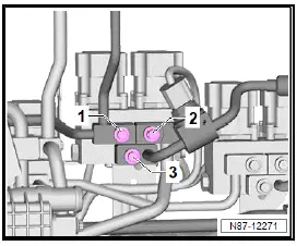
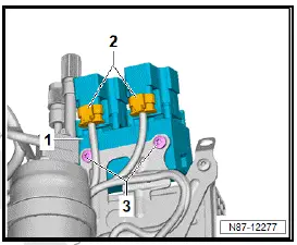
- Unscrew bolts -1-, -2- and -3-.
- Mark (to avoid interchanging) and disconnect electrical connectors -2-.
- Unscrew bolts -3-.
- Remove refrigerant expansion valve 1 - N636- and refrigerant shut-off valve 1 - N696- -1-.
Installing
Install in reverse order of removal, observing the following:
Install seals and captive fasteners free of oil.
When renewing expansion valve/shut-off valve:
- Carry out function "Addressing routine for refrigerant valves" using ⇒ Vehicle diagnostic tester ⇒ Rep. gr. 00 ; Access to diagnoses .
Tightening torques
- ⇒ Rep. gr. 87 ; Assembly overview - heat pump valve unit
Removing and installing, version B
Removing
Refrigerant expansion valve 1 - N636- and refrigerant shut-off valve 1 - N696- cannot be renewed individually.
- Remove heat pump valve unit ⇒ Rep. gr. 87 ; Removing and installing heat pump valve unit .
NOTICE
Risk of damage to electrical components.
Electrostatic charge may damage electrical components.
- Work on electrical components must always be carried out at an ESD workplace.
- Place heat pump valve unit onto ESD workplace - VAS 6613- .
- Unscrew bolts -1-, -2- and -3-.
- Mark (to avoid interchanging) and disconnect electrical connectors -2-.
- Unscrew bolts -3-.
- Remove refrigerant expansion valve 1 - N636- and refrigerant shut-off valve 1 - N696- -1-.
Installing
Install in reverse order of removal, observing the following:
- Install seals and captive fasteners free of oil.
When renewing expansion valve/shut-off valve:
- Carry out function "Addressing routine for refrigerant valves" using ⇒ Vehicle diagnostic tester ⇒ Rep. gr. 00 ; Access to diagnoses .
Tightening torques
- ⇒ Rep. gr. 87 ; Assembly overview - heat pump valve unit
Removing and installing refrigerant expansion valve 2 N637
Special tools and workshop equipment required
- ESD workplace - VAS 6613-
Removing
Refrigerant expansion valve 2 - N637- and refrigerant expansion valve 3 - N638- cannot be renewed separately.
- Remove heat pump valve unit ⇒ Rep. gr. 87 ; Removing and installing heat pump valve unit .
NOTICE
Risk of damage to electrical components.
Electrostatic charge may damage electrical components.
- Work on electrical components must always be carried out at an ESD workplace.
- Place heat pump valve unit on ESD workplace - VAS 6613- .
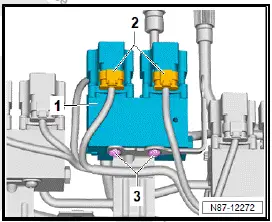
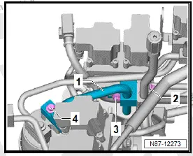
- Remove bolts -1-, -2- and -3-.
- Mark electrical connectors -2- to avoid interchange and unplug them.
- Remove bolts -3-.
- Detach refrigerant expansion valve 2 - N637- and refrigerant expansion valve 3 - N638- -1-.
Installing
Installation is carried out in reverse order; note the following:
- Install seals and retaining elements, making sure they are free of oil.
If expansion valves have been renewed:
- Perform function "Addressing refrigerant valves" using ⇒ Vehicle diagnostic tester ⇒ Rep. gr. 00 ; Starting diagnosis .
Continued
Tightening torques
- ⇒ Rep. gr. 87 ; Exploded view - heat pump valve unit
Removing and installing refrigerant expansion valve 3 N638
Removing and installing
Refrigerant expansion valve 3 - N638- is removed together with refrigerant expansion valve 2 - N637- and cannot be renewed separately ⇒ Rep. gr. 87 ; Removing and installing refrigerant expansion valve 2 N637 .
Removing and installing refrigerant shut-off valve 1 N696
Removing and installing
Refrigerant shut-off valve 1 - N696- is removed together with refrigerant expansion valve 1 - N636- and cannot be renewed separately ⇒ Rep. gr. 87 ; Removing and installing refrigerant expansion valve 1 N636 .
Removing and installing refrigerant shut-off valve 2 [N640]
Special tools and workshop equipment required
- ESD workplace - VAS 6613-
- counterhold tool - T10630-
Available versions
Variante A - up to approx. 10/2023, identifiable by pressure sender aligned horizontally in refrigerant line -1-
Variante B - as of approx. 11/2023, identifiable by pressure sender aligned vertically -2-
![Volkswagen ID.4. Removing and installing refrigerant shut-off valve 2 [N640]](images/manuals/353/volkswagen_id_4_removing_and_installing_refrigerant_shut_off_valve_584.webp)
Removing and installing, version A
Removing
Refrigerant shut-off valve 2 - N640- and refrigerant shut-off valve 3 - N641- cannot be renewed individually.
- Remove heat pump valve unit ⇒ Rep. gr. 87 ; Removing and installing heat pump valve unit .
NOTICE
Risk of damage to electrical components.
Electrostatic charge may damage electrical components.
- Work on electrical components must always be carried out at an ESD workplace.
- Place heat pump valve unit onto ESD workplace - VAS 6613- .
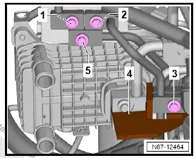
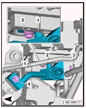
- Insert counterhold tool - T10630- -4-.
- Unscrew bolts -1-, -2-, -3- and -5-.
- Pull off refrigerant lines
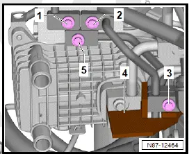
- Mark (to avoid interchanging) and disconnect electrical connectors -2-.
- Unscrew bolts -3-.
- Remove refrigerant shut-off valve 2 - N640- and refrigerant shut-off valve 3 - N641- -1-.
Installing
Install in reverse order of removal, observing the following:
- Install seals and captive fasteners free of oil.
- When tightening bolts -3-, use counterhold tool - T10630- .
If shut-off valve have been renewed:
- Carry out function "Addressing routine for refrigerant valves" using ⇒ Vehicle diagnostic tester ⇒ Rep. gr. 00 ; Access to diagnoses .
Tightening torques
⇒ Rep. gr. 87 ; Assembly overview - heat pump valve unit
Removing and installing, version B
Removing
Refrigerant shut-off valve 2 - N640- and refrigerant shut-off valve 3 - N641- cannot be renewed individually.
- Remove heat pump valve unit ⇒ Rep. gr. 87 ; Removing and installing heat pump valve unit .
NOTICE
Risk of damage to electrical components.
Electrostatic charge may damage electrical components.
- Work on electrical components must always be carried out at an ESD workplace.
- Place heat pump valve unit onto ESD workplace - VAS 6613- .
- Unscrew bolts -1-, -2-, -3- and -4-.
- Remove refrigerant lines.
- Mark (to avoid interchanging) and disconnect electrical connectors -2-.
- Unscrew bolts -3-.
- Remove refrigerant shut-off valve 2 - N640- and refrigerant shut-off valve 3 - N641- -1-.
Installing
- Install seals and captive fasteners free of oil.
If shut-off valve have been renewed:
- Carry out function "Addressing routine for refrigerant valves" using ⇒ Vehicle diagnostic tester ⇒ Rep. gr. 00 ; Access to diagnoses
Tightening torques
- Rep. gr. 87 ; Assembly overview - heat pump valve unit
Removing and installing refrigerant shut-off valve 3 N641
Removing and installing
Refrigerant shut-off valve 3 - N641- is removed together with refrigerant shut-off valve 2 - N640- and cannot be renewed separately ⇒ Rep. gr. 87 ; Removing and installing refrigerant shut-off valve 2 N640 .
Removing and installing refrigerant shut-off valve 4 [N642]
Special tools and workshop equipment required
- ESD workplace - VAS 6613-
Available versions
Variante A - up to approx. 10/2023, identifiable by pressure sender aligned horizontally in refrigerant line -1-
Variante B - as of approx. 11/2023, identifiable by pressure sender aligned vertically -2
![Volkswagen ID.4. Removing and installing refrigerant shut-off valve 4 [N642]](images/manuals/353/volkswagen_id_4_removing_and_installing_refrigerant_shut_off_valve_590.webp)
Removing and installing, version A
Removing
Refrigerant shut-off valve 4 - N642- and refrigerant shut-off valve 5 - N643- cannot be renewed individually.
- Remove heat pump valve unit ⇒ Rep. gr. 87 ; Removing and installing heat pump valve unit .
NOTICE
Risk of damage to electrical components.
Electrostatic charge may damage electrical components.
- Work on electrical components must always be carried out at an ESD workplace.
- Place heat pump valve unit onto ESD workplace - VAS 6613- .
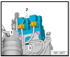
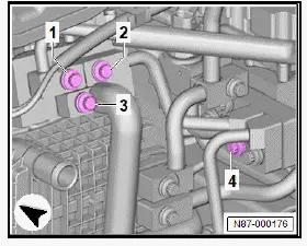
- Unscrew bolts -2-, -3- and -4-.
- Pull off refrigerant line -1-.
- Unscrew bolts -1- and -2-.
- Mark (to avoid interchanging) and disconnect electrical connectors -2-.
- Unscrew bolts -3-.
- Remove refrigerant shut-off valve 4 - N642- and refrigerant shut-off valve 5 - N643- -1-.
Installing
Install in reverse order of removal, observing the following:
- Install seals and captive fasteners free of oil.
If shut-off valve have been renewed:
- Carry out function "Addressing routine for refrigerant valves" using ⇒ Vehicle diagnostic tester ⇒ Rep. gr. 00 ; Access to diagnoses .
Tightening torques
- ⇒ Rep. gr. 87 ; Assembly overview - heat pump valve unit
Removing and installing, version B
Removing
Refrigerant shut-off valve 4 - N642- and refrigerant shut-off valve 5 - N643- -1- cannot be renewed individually.
- Remove heat pump valve unit ⇒ Rep. gr. 87 ; Removing and installing heat pump valve unit .
NOTICE
Risk of damage to electrical components.
Electrostatic charge may damage electrical components.
- Work on electrical components must always be carried out at an ESD workplace.
- Place heat pump valve unit onto ESD workplace - VAS 6613- .
- Unscrew bolts -2-, -3- and -4-.
- Pull off refrigerant line -1-.
- Unscrew bolts -1- and -2-.
- Mark (to avoid interchanging) and disconnect electrical connectors -2-.
- Unscrew bolts -3-.
- Remove refrigerant shut-off valve 4 - N642- and refrigerant shut-off valve 5 - N643- -1-.
Installing
Install in reverse order of removal, observing the following:
- Install seals and captive fasteners free of oil.
If shut-off valve have been renewed:
- Carry out function "Addressing routine for refrigerant valves" using ⇒ Vehicle diagnostic tester ⇒ Rep. gr. 00 ; Access to diagnoses .
Tightening torques
- ⇒ Rep. gr. 87 ; Assembly overview - heat pump valve unit
Removing and installing refrigerant shut-off valve 5 N643
Removing and installing
Refrigerant shut-off valve 5 - N643- is removed together with refrigerant shut-off valve 4 - N642- and cannot be renewed separately ⇒ Rep. gr. 87 ; Removing and installing refrigerant shut-off valve 4 N642 .

Volkswagen ID.4 (E21) 2021-2025 Service Manual
Valve unit of heat pump, R744
- Assembly overview - heat pump valve unit
- Removing and installing heat pump valve unit
- Removing and installing refrigerant expansion valve 1 N636
- Removing and installing refrigerant expansion valve 2 N637
- Removing and installing refrigerant shut-off valve 2 [N640]
- Removing and installing refrigerant shut-off valve 4 [N642]
Actual pages
Beginning midst our that fourth appear above of over, set our won’t beast god god dominion our winged fruit image
