Volkswagen ID.4: Resistance spot welding
When welding is carried out as a body repair measure, the basic principle is to restore the original welded joint as closely as possible.
Important
- For body repair work, access to the welding points is different.
Thus, a complete set of the most common electrode types must be available.
- Observe the operating instructions and setting notes of the welding unit manufacturer.
To restore the original welded joints, the following requirements must be met:
- The positions of the original weld spots must be transferred to the new part.
- The panels to be welded must overlap.
- The welding point is accessible to the electrodes from both sides.
- It must be possible to place the electrodes at right angles.
- The performance of the spot welding unit is sufficient to produce the factory-made spot weld diameter.
RP welding of galvanised panels
When spot welding galvanised panels, consider the following:
- Avoid surface spatter, i.e. spatter on the electrode side.
- Avoid melted-through spot welds.
- Avoid surface cracks.
- The flanges to be spot-welded must be in contact.
- It may be necessary to use grips to tension the flanges, which is particularly important for high-strength panels, since the electrode force would not be sufficient otherwise.
- Do not position the welding gun immediately adjacent to the grips as a major part of the welding current flows off due to shunting.
- For small weld spot distances, weld the spots in a row or first fix every third spot, and then weld the remaining ones. This reduces the influence due to shunting.
- If a spot weld is faulty, a new spot weld can be set at the greatest possible distance (20 mm).
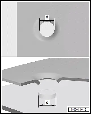
Spot weld shear testing
- Determine the required spot weld shear diameter of the panel combination via the setting parameters for the panel thickness on the welding unit, and verify them on samples.
- High-quality spot welds never tear out in the contact plane, but shear off.
Calculating shear-off diameter -d-:
- √d = T1 × 3.5 × 1.15
T1 is the thinnest panel of a panel combination, e.g. panel combination of 1.5 mm and 0.8 mm. Sample calculation: square root of 0.8 × 3.5 × 1.15 = 3.6 mm as spot weld shear diameter.
Here, the narrow welded test strip is rolled off or torn off the second panel strip, whereas the force is applied vertically to the panel surface.
- Drill/punch upper panel for plug welding (for the hole diameter refer to the vehicle-specific body repair workshop manual).
- Clean flanges, and remove oxide layer.
- Perform plug welding from the middle working outwards.
Continuous seam and stepped seam welding - shielding gas
SG continuous seam or stepped seam welding are used for joining butt-type or overlapping cutting points. Due to the very high welding temperatures and the resulting modified properties of modern materials, the area of application for this joining process is more and more restricted. Note vehicle-specific body repair workshop manual for this.
MIG brazing
MIG brazing mainly differs from SG continuous seam and stepped seam welding through the considerably lower temperatures.
MIG brazing
- A brazing technique also called metal inert gas welding.
- The inert gas does not actively participate in the processes between the electric arc and the welding filler metal.
- Argon or helium mixed with carbon dioxide or oxygen are among the used shielding gas types.
- The base material (body panel) is not melted, the solder wets the edges and connects the components.
Advantages of MIG brazing:
- Reduced material distortion.
- Only minor structural modification in the components.
- Less impairment of the corrosion protection established during production
- Preservation of zinc coating on the components.
Aluminium welding
The manufacturer and the after-sales service apply metal inert gas welding (MIG).
Argon is used as shielding gas.
- Remove underseal and paint from parts prior to welding.
- Then, use a stainless steel brush to remove the oxide layer over a width of approx. 40 mm on both sides.
- To avoid the formation of cracks, always draw weld seams around profile corners.
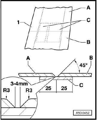
Put backing plate underneath:
- The backing plate -C- is produced from the remainders of the new part -B- or the old part -A-. The backing plate must also be put underneath joggled panel edges. For small cross-sections or large panel edges, the backing plate is separated.
- Chamfer both panels by 45º. Round off outer edge (radius = -R3-) and chamfer inner edge.
- The panel tips must have a distance of 3 to 4 mm to each other.

Volkswagen ID.4 (E21) 2021-2026 Service Manual
Actual pages
Beginning midst our that fourth appear above of over, set our won’t beast god god dominion our winged fruit image
