Volkswagen ID.4: Senders/sensors/control units
- Removing and installing front parking aid senders [G252]/[G253]/[G254]/[G255]
- Removing and installing rear parking aid senders [G203]/[G204]/[G205]/[G206]
- Removing and installing front park assist steering senders [G568]/[G569]
- Removing and installing rear park assist steering senders [G716]/[G717]
- Removing and installing adaptive cruise control unit [J428]
- Removing and installing control unit for overhead view camera [J928]
- Removing and installing left/right overhead view camera R244/R245
- Removing and installing parking aid control unit [J446]
- Removing and installing reversing camera [R189]
Removing and installing front parking aid senders [G252]/[G253]/[G254]/[G255]
The front right parking aid sender -G252-, front centre right parking aid sender -G253-, front centre left parking aid sender -G254- and front left parking aid sender -G255- will henceforth be referred to as "sender".
Removing
Outer rear senders:
- Detach front wheel housing liner ⇒ General body repairs, exterior; Rep. gr. 66; Wheel housing liner; Removing and installing front wheel housing liner.
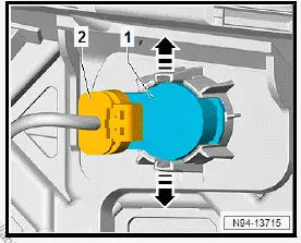
- Press locking devices in direction of -arrow- while simultaneously pressing sender -1- inwards from outside.
![Volkswagen ID.4. Removing and installing front parking aid senders [G252]/[G253]/[G254]/[G255]](images/manuals/353/volkswagen_id_4__g252_g253_g254_g255__913.webp)
- Disconnect electrical connector -2-, and pull it in a straight line off sender -1-.
- Remove sender -1-.
All vehicles (continued)
Inner rear senders:
- Remove bumper cover ⇒ General body repairs, exterior; Rep. gr. 63; Front bumper; Removing and installing bumper cover.
- Press locking devices in direction of -arrow- while simultaneously pressing sender -1- inwards from outside.
- Disconnect electrical connector -2-, and pull it in a straight line off sender -1-.
- Remove sender -1-.
All vehicles (continued)
Installing
Install in reverse order of removal, observing the following:
NOTICE
Malfunctions due to the use of an unsuitable or damaged decoupling ring -3-.
- Do not turn decoupling ring -3- on the sender head.
- Renew decoupling ring -3- if unsuitable or damaged.
- Check decoupling ring -3- on sender -1- for damage.
- Push electrical connector -2- in straight line on sender -1- and engage it.
- When inserting sender -1- in sender retainer, make sure that the decoupling ring -3- is seated correctly on the sender head.
- Insert sender -1- in a straight line into sender retainer.
Important
- Locking devices of sender retainer must engage when installing sender -1-.
Removing and installing rear parking aid senders [G203]/[G204]/[G205]/[G206]
The rear left parking aid sender -G203-, rear centre left parking aid sender -G204-, rear centre right parking aid sender -G205- and rear right parking aid sender -G206- will henceforth be referred to as "sender".
Removing
Outer rear senders:
- Press locking devices in direction of -arrow- while simultaneously pressing sender -1- inwards from outside.
![Volkswagen ID.4. Removing and installing rear parking aid senders [G203]/[G204]/[G205]/[G206]](images/manuals/353/volkswagen_id_4__g252_g253_g254_g255__916.webp)
- Disconnect electrical connector -2-, and pull it in a straight line off sender -1-.
- Remove sender -1-.
All vehicles (continued)
Inner rear senders:
- Remove bumper cover ⇒ General body repairs, exterior; Rep. gr. 63; Rear bumper; Removing and installing bumper cover.
- Press locking devices in direction of -arrow- while simultaneously pressing sender -1- inwards from outside.
![Volkswagen ID.4. Removing and installing rear parking aid senders [G203]/[G204]/[G205]/[G206]](images/manuals/353/volkswagen_id_4__g252_g253_g254_g255__917.webp)
- Disconnect electrical connector -2-, and pull it in a straight line off sender -1-.
- Remove sender -1-.
All vehicles (continued)
Installing
Install in reverse order of removal, observing the following:
NOTICE
Malfunctions due to the use of an unsuitable or damaged decoupling ring -3-.
- Do not turn decoupling ring -3- on the sender head.
- Renew decoupling ring -3- if unsuitable or damaged.
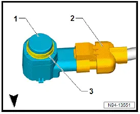
- Check decoupling ring -3- on sender -1- for damage.
![Volkswagen ID.4. Removing and installing rear parking aid senders [G203]/[G204]/[G205]/[G206]](images/manuals/353/volkswagen_id_4__g252_g253_g254_g255__918.webp)
- Push electrical connector -2- in straight line on sender -1- and engage it.
- When inserting sender -1- in sender retainer, make sure that the decoupling ring -3- is seated correctly on the sender head.
- Insert sender -1- in a straight line into sender retainer.
Important
- Locking devices of sender retainer must engage when installing sender -1-.
Removing and installing front park assist steering senders [G568]/[G569]
The front left sender for park assist steering on left side of vehicle -G568- and front right sender for park assist steering on right side of vehicle -G569- will henceforth be referred to as "sender".
Removing
- Detach front wheel housing liner ⇒ General body repairs, exterior; Rep. gr. 66; Wheel housing liner; Removing and installing front wheel housing liner.
- Press locking devices in direction of -arrow- while simultaneously pressing sender -1- inwards from outside.
![Volkswagen ID.4. Removing and installing front park assist steering senders [G568]/[G569]](images/manuals/353/volkswagen_id_4_removing_and_installing_front_park_assist_steering_919.webp)
- Disconnect electrical connector -2-, and pull it in a straight line off sender -1-.
- Remove sender -1-.
Installing
Install in reverse order of removal, observing the following:
NOTICE
Malfunctions due to the use of an unsuitable or damaged decoupling ring -3-.
- Do not turn decoupling ring -3- on the sender head.
- Renew decoupling ring -3- if unsuitable or damaged.
- Check decoupling ring -3- on sender -1- for damage
![Volkswagen ID.4. Removing and installing front park assist steering senders [G568]/[G569]](images/manuals/353/volkswagen_id_4_removing_and_installing_front_park_assist_steering_920.webp)
- Push electrical connector -2- in straight line on sender -1- and engage.
- When inserting sender -1- in sender retainer, make sure that the decoupling ring -3- is seated correctly on the sender head.
- Insert sender -1- in a straight line into sender retainer.
Important
- Locking devices of sender retainer must engage when installing sender -1-.
Removing and installing rear park assist steering senders [G716]/[G717]
The rear left park assist steering sender -G716- and rear right park assist steering sender -G717- will henceforth be referred to as "sender".
Removing
- Detach rear wheel housing liner ⇒ General body repairs, exterior; Rep. gr. 66; Wheel housing liner; Removing and installing rear wheel housing liner.
- Press locking devices in direction of -arrow- while simultaneously pressing sender -1- inwards from outside.
![Volkswagen ID.4. Removing and installing rear park assist steering senders [G716]/[G717]](images/manuals/353/volkswagen_id_4_removing_and_installing_rear_park_assist_steering_921.webp)
- Disconnect electrical connector -2-, and pull it in a straight line off sender -1-.
- Remove sender -1-.
Installing
Install in reverse order of removal, observing the following:
NOTICE
Malfunctions due to the use of an unsuitable or damaged decoupling ring-3-
- Do not turn decoupling ring -3- on the sender head.
- Renew decoupling ring -3- if unsuitable or damaged.
- Check decoupling ring -3- on sender -1- for damage
![Volkswagen ID.4. Removing and installing rear park assist steering senders [G716]/[G717]](images/manuals/353/volkswagen_id_4_removing_and_installing_rear_park_assist_steering_922.webp)
- Push electrical connector -2- in straight line on sender -1- and engage.
- When inserting sender -1- in sender retainer, make sure that the decoupling ring -3- is seated correctly on the sender head.
- Insert sender -1- in a straight line into sender retainer.
Important
Locking devices of sender retainer must engage when installing sender -1-.
Removing and installing adaptive cruise control unit [J428]
Removing
Adaptive cruise control unit -J428- is called control unit in this document.
If the control unit is renewed, perform the test plan for the renewal of the control unit:
- Carry out function "Adaptive cruise control unit" using ⇒ Vehicle diagnostic tester ⇒ Rep. gr. 00; Access to diagnoses.
Continued
- Open bonnet.
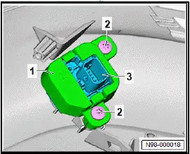
- Disconnect electrical connector -2-.
![Volkswagen ID.4. Removing and installing adaptive cruise control unit [J428]](images/manuals/353/volkswagen_id_4_removing_and_installing_adaptive_cruise_control_un_923.webp)
- Unscrew bolts -1-.
- Remove bracket -3- with control unit.
Installing
Install in reverse order of removal, observing the following:
If the control unit has been renewed, conclude the test plan for the renewal of the control unit:
- Conclude function "Adaptive cruise control unit" using ⇒ Vehicle diagnostic tester ⇒ Rep. gr. 00; Access to diagnoses.
Continued
- ⇒ Rep. gr. 98; Adjusting/calibrating adaptive cruise control unit
Tightening torques
Removing and installing lane change assist control unit [J769]/[J770]
The lane change assist control unit -J769- and lane change assist control unit 2 -J770- will henceforth be referred to as "control unit".
Removal and installation are described for the left vehicle side as an example.
Removing
- Remove bumper cover ⇒ General body repairs, exterior; Rep. gr. 63; Rear bumper; Removing and installing bumper cover.
- Disconnect electrical connector -3-.
![Volkswagen ID.4. Removing and installing lane change assist control unit [J769]/[J770]](images/manuals/353/volkswagen_id_4_removing_and_installing_adaptive_cruise_control_un_925.webp)
- Release locking device -2-.
- Swing control unit -1- in direction of -arrow-, and remove it.
- To remove bracket of control unit -1-, unscrew nut, and remove bracket.
Installing
Install in reverse order of removal, observing the following:
Tightening torques

Removing and installing lane change assist warning lamp in exterior mirror
Removal and installation are described for the left vehicle side as an example.
Removing
- Remove upper mirror cover ⇒ General body repairs, exterior; Rep. gr. 66; Exterior mirrors; Removing and installing upper mirror cover.
- Push area -3- in direction of -arrow A-, and hold it in that position.
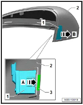
- Press warning lamp -1- in direction of -arrow B- out of mirror cover -2-.
Installing
Install in reverse order of removal.
Removing and installing control unit for overhead view camera [J928]
Removing and installing control unit for overhead view camera [J928]
Control unit for overhead view camera -J928- is referred to hereafter as control unit.
Removing
If the control unit is renewed, perform the test plan for renewal of the control unit:
- Carry out function "Renew control unit for overhead view camera" using ⇒ Vehicle diagnostic tester ⇒ Rep. gr. 00; Access to diagnoses.
Continued
- Remove seat pan ⇒ General body repairs, interior; Rep.
gr. 72; Rear seats; Removing and installing seat pan.
- Separate electrical connectors.
![Volkswagen ID.4. Removing and installing control unit for overhead view camera [J928]](images/manuals/353/volkswagen_id_4_removing_and_installing_control_unit_for_overhead_928.webp)
- Release spreader rivets -2-, and remove control unit -1-.
Installing
Install in the reverse order of removal, observing the following:
If the control unit has been renewed, conclude the test plan for the renewal of the control unit:
- Conclude function "Renew control unit for overhead view camera" using ⇒ Vehicle diagnostic tester ⇒ Rep. gr. 00; Access to diagnoses.
Removing and installing holder for control unit for overhead view camera [J928]
Holder for control unit for overhead view camera -J928- is referred to hereafter as holder.
Removing
- Remove control unit for overhead view camera -J928- ⇒ Rep. gr. 98; Removing and installing control unit for overhead view camera [J928].
- Unscrew nuts -1-.
![Volkswagen ID.4. Removing and installing holder for control unit for overhead view camera [J928]](images/manuals/353/volkswagen_id_4_removing_and_installing_control_unit_for_overhead_929.webp)
- Detach holder.
Installing
Install in the reverse order of removal, observing the following:
Tightening torques
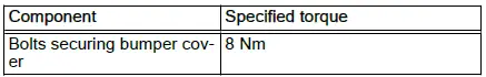
Component / Specified torque
Nut on bracket / 8 Nm
Removing and installing left/right overhead view camera R244/R245
Left overhead view camera -R244- and right overhead view camera -R245- are called camera in this document.
Removal and installation are described for left vehicle side as an example.
Removing
- Remove upper mirror cover ⇒ General body repairs, exterior; Rep. gr. 66; Exterior mirrors; Removing and installing upper mirror cover.
- Unscrew bolts -2-.
- Remove bracket -1- with camera -3-.
- Separate electrical connector and remove camera -3- from bracket -1-.
Installing
Install in the reverse order of removal, observing the following:
- ⇒ Rep. gr. 98; Calibrate overhead view camera.
Tightening torques
- ⇒ General body repairs, exterior; Rep. gr. 66; Exterior mirror; Assembly overview - exterior mirror
Removing and installing left/right overhead view camera R244/R245
Removing and installing front camera for driver assist systems [R242]
Removing
Front camera for driver assist systems -R242- is called front camera in this document.
- Remove bottom cover ⇒ General body repairs, interior; Rep.
gr. 68; Interior mirror; Removing and installing interior mirror.
- Unclip front camera -2- in direction of -arrow A-, and remove it in direction of -arrow B-.
![Volkswagen ID.4. Removing and installing front camera for driver assist systems [R242]](images/manuals/353/volkswagen_id_4_camera_r244_r245_931.webp)
- Disconnect electrical connector -1-.
Installing
Install in reverse order of removal, observing the following:
Important
The field of view of the front camera on the inside of the windscreen must not be fogged or soiled.
- Clean field of view of front camera with cleaning solution ⇒ Electronic parts catalogue (ETKA).
- ⇒ Rep. gr. 98; Calibrate front camera for driver assist systems R242.
Removing and installing windscreen heater for front sensors [Z113]
Windscreen heater for front sensors -Z113- is referred to hereafter as windscreen heater.
Front camera for driver assist systems -R242- is called front camera in this document.
Removing
- Remove front camera ⇒ Rep. gr. 98; Removing and installing front camera for driver assist systems [R242].
- Move aside electrical wire, and disconnect electrical connector -3-.
![Volkswagen ID.4. Removing and installing windscreen heater for front sensors [Z113]](images/manuals/353/volkswagen_id_4_camera_r244_r245_932.webp)
- Release locking device -2-.
- Remove window heating -1- in direction of -arrow-.
Installing
Install in the reverse order of removal, observing the following:
Important
- The field of view of the front camera on the inside of the windscreen must not be steamed up or soiled.
- Clean field of view of front camera with cleaning solution ⇒ Electronic parts catalogue (ETKA).
- ⇒ Rep. gr. 98; Calibrate front camera for driver assist systems R242.
Removing and installing parking aid control unit [J446]
The parking aid control unit -J446- will henceforth be referred to as "control unit".
Removing
- Remove right luggage compartment side trim ⇒ General body repairs, interior; Rep. gr. 70; Luggage compartment trims; Removing and installing luggage compartment side trim.
- Unscrew bolts -2-, and remove control unit -1-.
![Volkswagen ID.4. Removing and installing parking aid control unit [J446]](images/manuals/353/volkswagen_id_4__j446__933.webp)
- Disconnect electrical connectors.
Installing
Install in reverse order of removal, observing the following:
Removing and installing front camera for driver assist systems [R242]
Removing
The front overhead view camera -R243- will henceforth be referred to as "camera".
- Remove badge at front ⇒ General body repairs, exterior; Rep. gr. 66; Lettering and badges; Removing and installing badges at front.
- Disconnect electrical connector.
- Push locking devices in direction of -arrow-, and remove bracket -2-.
![Volkswagen ID.4. Removing and installing front camera for driver assist systems [R242]](images/manuals/353/volkswagen_id_4__j446__934.webp)
- Pull camera -1- out of front badge.
![Volkswagen ID.4. Removing and installing front camera for driver assist systems [R242]](images/manuals/353/volkswagen_id_4__j446__935.webp)
Installing
Install in reverse order of removal, observing the following:
Important
- Make sure that camera is correctly seated.
- The bracket must be heard to engage.
- ⇒ Rep. gr. 98; Calibrate overhead view camera.
Removing and installing reversing camera [R189]
Reversing camera -R189- will henceforth be referred to as "camera".
Removing
- Remove rear lid handle ⇒ General body repairs, exterior; Rep. gr. 55; Rear lid; Removing and installing rear lid handle.
- Release locking device -2-, and remove camera -1- in direction of -arrow-.
![Volkswagen ID.4. Removing and installing reversing camera [R189]](images/manuals/353/volkswagen_id_4_removing_and_installing_reversing_camera_r189__936.webp)
Installing
Install in the reverse order of removal, observing the following:
- ⇒ Rep. gr. 98; Calibrate reversing camera [R189].
Removing and installing rear overhead view camera [R246]
The rear overhead view camera -R246- will henceforth be referred to as "camera".
Removing
- Remove rear lid handle ⇒ General body repairs, exterior; Rep. gr. 55; Rear lid; Removing and installing rear lid handle.
- Release locking device -2-, and remove camera -1- in direction of -arrow-.
![Volkswagen ID.4. Removing and installing rear overhead view camera [R246]](images/manuals/353/volkswagen_id_4_removing_and_installing_reversing_camera_r189__937.webp)
Installing
Install in the reverse order of removal, observing the following:
- ⇒ Rep. gr. 98; Calibrate overhead view camera system.

Volkswagen ID.4 (E21) 2021-2025 Service Manual
Senders/sensors/control units
- Removing and installing front parking aid senders [G252]/[G253]/[G254]/[G255]
- Removing and installing rear parking aid senders [G203]/[G204]/[G205]/[G206]
- Removing and installing front park assist steering senders [G568]/[G569]
- Removing and installing rear park assist steering senders [G716]/[G717]
- Removing and installing adaptive cruise control unit [J428]
- Removing and installing control unit for overhead view camera [J928]
- Removing and installing left/right overhead view camera R244/R245
- Removing and installing parking aid control unit [J446]
- Removing and installing reversing camera [R189]
Actual pages
Beginning midst our that fourth appear above of over, set our won’t beast god god dominion our winged fruit image
