Volkswagen ID.4: Equipment
- Assembly overview - net partition
- Removing and installing net partition bracket
- Removing and installing sun visor
- Removing and installing roof grab handle
Assembly overview - net partition
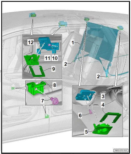
- Net partition
- Fastening ring
- Upper rear net partition bracket
- ⇒ Rep. gr. 68 ; Removing and installing upper net partition bracket
- Retaining frame
- Trim
- ⇒ Rep. gr. 68 ; Removing and installing upper net partition bracket
- Bolt
- Qty. 2
- 8 Nm
- Bolt
- Qty. 2
- 20 Nm
- Lower net partition bracket
- ⇒ Rep. gr. 68 ; Removing and installing lower net partition bracket
- Retaining frame
- Bolt
- Qty. 2
- 8 Nm
- Trim
- ⇒ Rep. gr. 68 ; Removing and installing upper net partition bracket
- Upper front net partition bracket
- ⇒ Rep. gr. 68 ; Removing and installing upper net partition bracket
Assembly overview sun visors
The overview is shown for the left side of vehicle as an example.
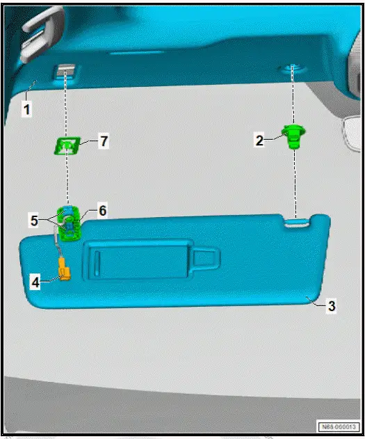
- Moulded headliner
- ⇒ Rep. gr. 70 ; Removing and installing moulded headliner
- Sun visor centre mount
- ⇒ Rep. gr. 68 ; Removing and installing sun visor centre mount
- Sun visor
- ⇒ Rep. gr. 68 ; Removing and installing sun visor
- Electrical connector
- Retaining clip
- qty. 2
- Cap
- qty. 2
- Clamping plate
Removing and installing net partition bracket
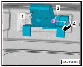
Removing and installing upper net partition bracket
Removing
Removal and installation are described for left side of vehicle as an example.
- Lower the moulded headliner ⇒ Rep. gr. 70 ; Removing and installing moulded headliner .
- Unscrew bolt -2-.
- Remove upper net partition bracket -1- in direction of -arrow A-.
Installing
Install in reverse order of removal, observing the following:
Tightening torques
- ⇒ Rep. gr. 68 ; Assembly overview - net partition
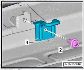
Removing and installing lower net partition bracket
Removing
Removal and installation are described for the left side of vehicle as an example.
- Remove front sill panel moulding ⇒ Rep. gr. 70 ; Removing and installing front sill panel moulding .
- Move front seat to foremost position.
- Unscrew bolt -2-.
- Remove lower net partition bracket -1-.
Installing
Install in reverse order of removal, observing the following:
Tightening torques
- ⇒ Rep. gr. 68 ; Assembly overview - net partition
Removing and installing sun visor
Special tools and workshop equipment required
- pliers - T10558A
Removing
Removal and installation are described for the left side of vehicle as an example.
- Swing sun visor towards front.
- Remove illuminated vanity mirror [W20]/[W14].⇒ Electrical system; Rep. gr. 96 ; Lights; Removing and installing illuminated vanity mirror [W20]/[W14] .
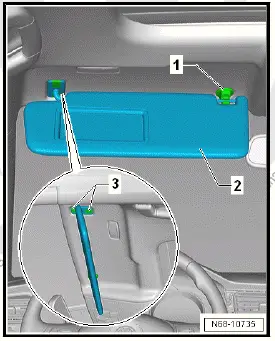
- Detach sun visor -2- from sun visor centre mount -1-, and fold it aside.
- Lever off caps -3- using a small screwdriver.
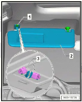
- Position pliers - T10558A- centrally in retaining clips -3-.
- Detach foremost (when seen in direction of travel) retaining clip -3- in sun visor bracket -1- using pliers - T10558A- .
- Pull sun visor -2- lightly downwards to prevent foremost retaining clip -3- from re-engaging.
- Detach rearmost (when seen in direction of travel) retaining clip -3- in sun visor bracket -1- using pliers - T10558A- .
- Pull sun visor -2- downwards.
NOTICE
Risk of damage to electrical wiring by pulling too forcefully.
- Carefully pull electrical wiring out of opening.
- Disconnect electrical connector.
- Remove clamping plate.
- Remove sun visor.
Installing
Install in reverse order of removal, observing the following:
- Wrap electrical connector with one layer of foam tape.
- Grasp with one finger into recess in vanity mirror light.
- Pull moulded headliner slightly downwards.
- Position electrical connector between moulded headliner and roof cross member.
- Engage foremost (when seen in direction of travel) retaining clip.
- Engage rearmost (when seen in direction of travel) retaining clip.
- Make sure that both retaining clips are properly engaged.
Removing and installing sun visor centre mount
Removing
Removal and installation are described for the left side of vehicle as an example.
- Detach sun visor and fold it aside.
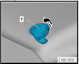
- Turn sun visor centre mount -1- in direction of -arrow-.
- Remove sun visor centre mount -1- downwards.
Installing
Install in reverse order of removal.
Removing and installing roof grab handle
Special tools and workshop equipment required
-
release tool - T10518A
Removing
Removal and installation are described for the left side of vehicle as an example.
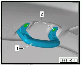
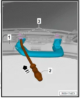
- Fold roof grab handle -1-.
- Unclip caps -2- using commercially available plastic wedge.
- Fold roof grab handle -1- downwards, and hold it there.
- Push release tool - T10518A- -2- in direction of -arrow- until retaining clip -3- is released.
- Pull release tool - T10518A- -2- with roof grab handle -1- in opposite direction of -arrow-.
- Repeat procedure for remaining retaining clip -3-while holding roof grab handle -1- under tension to prevent retaining clip -3- from engaging again.
- Detach roof grab handle -1-.
Installing
Install in reverse order of removal, observing the following:
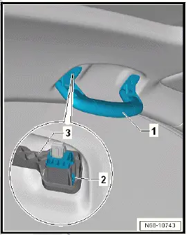
Important
- It is compulsory to install a spacer.
- Engage roof grab handle -1- in spacer -3-.
Important
- Locking devices -2- must engage.
- Position roof grab handle -1- properly, and push it into body until it can be heard to engage.

Volkswagen ID.4 (E21) 2021-2025 Service Manual
Equipment
- Assembly overview - net partition
- Removing and installing net partition bracket
- Removing and installing sun visor
- Removing and installing roof grab handle
Actual pages
Beginning midst our that fourth appear above of over, set our won’t beast god god dominion our winged fruit image
